2017年3月15日星期三

Type A MTP Cassette and Type B MTP Cassette: When and Where to Use?

Modular system, which allows for rapid deployment of high density data center infrastructure and improved troubleshooting and reconfiguration during MACs, is more and more popular. MTP cassette, topic of this post, is such a module. It provides a secure transition between MTP and LC or SC discreet connectors, and is used to interconnect MTP backbone cabling with LC or SC patch cables.

MTP Cassette Appearance
MTP fiber optic cassettes are pre-terminated and pre-tested enclosed units. They contain 12-fiber or 24-fiber factory terminated fan-outs inside. MTP modular cassettes serve to “transition” small diameter ribbon cables terminated with MPO connector(s) to the more common LC or SC interface used on the transceiver terminal equipment. Typically, the fan-outs incorporate LC, SC connectors plugged into adapters on the front side of the cassette and MPO connector(s) plugged into MPO adapter(s) mounted at the rear of the cassette. One or more MPO fan-out assemblies can be installed inside the cassette to connect up to two 12-fiber ribbon cables for a total of 24 fibers. Alignment pins are pre-installed in the MPO connector located inside the cassette. These pins precisely align the mating fibers in the MPO connectors at either end of the array cables that plug into the cassettes.

12-fiber MTP LC cassette and 24 fiber MTP LC cassette

MTP Cassette Polarity: Method A or Method B
The transition inside a MTP cassette, the connector keying for the MTP cassette module and the corresponding MPO array cables are completely defined for all three connectivity methods listed in the TIA standard as described in the previous post—polarity methods for MTP/MPO system. A common transition, factory installed inside a cassette, is used for all of the three methods. The adapter mounted at the rear of a cassette defines it as either Method A or Method B MTP modular cassette.

Method A MTP Cassette vs. Method B MTP Cassette
Method A MTP cassette makes a “key up to key down” connection between the internal MPO connector and the MPO array cable connector. Method B MTP cassette makes a “key up to key up” connection. The Method B cassette will not allow single-mode angle polish mated pair connections due to the fact that the angles of the mating connectors are not complementary. This prevents a Method B MTP cassette module or adapter from being used in single-mode applications requiring low return losses, a significant limitation with connectivity Method B. The difference between Method A and Method B MTP fiber optic cassette is the orientation of the internal MPO connector with respect to the mating with MPO array cable connector.

Connectivity Rules of Method A and Method B MTP Cassette
The components deployed for multiple duplex signals include a MTP cassette at each end. Pre-terminated 12-fiber trunk cables connect to the MPO adapter on the back of the two cassettes, and duplex patch cords are used to connect the equipment to the front of the cassettes. There are two types of patch cords “A-to-B” and “A-to-A” and three types of trunk cables “Type A”, “Type B”, “Type C” shown in the following pictures.

duplex patch cord
Type A MTP trunk cable, Type B MTP trunk cable, Type C MTP trunk cable

The following picture clearly shows the connection rules of every component required for the three connectivity methods.

polarity methods for Method A, Method B, Method C
From the picture, we can summarize following connection points:
  • Connectivity Method A is the most straight forward but requires a different patch cord at one end.
  • Connectivity Method B uses the same patch cord at both ends, but the cassettes (circled in red) must be flipped over at one end so that the fiber that originated in position 1 is mapped to position 12.
  • Connectivity Method C is a variant of Method A, but with the cross-over implemented in the trunk cable instead of the patch cord.
Note: No matter which method is selected, there must be a pair-wise flipping (A-to-B polarity swap) that takes place at some point in the link. If the pair-wise flipping does not occur in the cassette then the pair-wise flipping must occur in the duplex patch cord or the MPO trunk cable and/or adapters.

The following picture shows an illustration of the connectivity rules. The numbers shown next to the adapters on the outside of the cassette and the MPO connectors are fiber port designations. The numbers shown in bold next to the adapters on the inside of the cassette are fiber number designations.

illustration for Method A, Method B and Method C 

Summary
MTP cassette, containing factory controlled and tested MPO/MTP-LC fanouts, delivers high optical performance, rapid and error-free installation and reliable robust operation. Using Type A MTP cassette or Type B MTP cassette is closely related to the other components in the whole system. The best way to maintain correct optical polarity is to choose a standards-based approach and adhere to it throughout an installation. Incorrect connections violating the proper polarity will result in a link failure and possibly damage to critical optoelectronic components. It is best for installers and end-users to buy MTP cassette from a supplier adhering to TIA standards. FS.COM is such a MTP cassette modules manufacturer, who provides both 12 core and 24 core MTP/MPO fiber optic plug-n-play cassettes with low price.

2017年3月9日星期四

MTP-8 Solution: Future-Proof Connectivity in Data Center

In most data centers, MTP cable is widely used for high density application. MTP-12 connectivity and MTP-24 connectivity are the two common types of cabling connections, which use links based on increments of 12 and 24, such as 12-fiber trunk cables and 24-fiber trunk cables. In addition to MTP-12 and MTP-24, there is another MTP solution—MTP-8. In a MTP-8 solution or Base-8 solution, 8-fiber trunk cables, 24-fiber or 32-fiber trunk cables can be used to transmit data. In brief, MTP-8 solutions use cable links based on increments of the number “eight”. This post will explain the benefits of MTP-8 solution and show its application in 10G/40G data centers.

Why MTP-8 Appears?
 
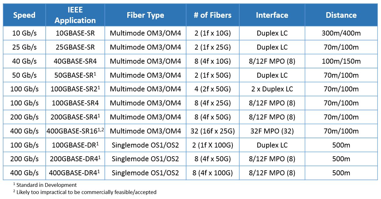
With MTP-12 and MTP-24 using in the data center for years, you may ask why there is still a need for MTP-8? In fiber optic industry, optical transceiver roadmap changes rapidly from 10G—40G—100G and even up to 400G (see the picture below). With faster speeds spreading out into data center racks and SANs, there is a need for a more manageable grouping. For 40G connections and above, data is usually carried over eight fibers, and terminated at the switch in a MTP-8 QSFP transceiver which combines eight fibers.

40G/100G/400G use MTP-8 solution 

From the picture, we can see that for Ethernet transmission ranging from 40G to 400G, all roads lead to 2-fiber and 8-fiber solution. For 40G/100G and future 400G applications, the use of 12-fiber MTP solution would result in 33% of the optical fibers unused. Thus it is expected that for 400G application, MTP-8 will gain widespread market acceptance.

MTP-8 Solution Benefits
 
Flexibility and 100% fiber utilization are the primary advantages of MTP-8 solution. Being wholly divisible by number “2”, MTP-8 solution can be easily used for two-fiber transceiver systems, just as MTP-12 solution can be. And for those who have deployed 12-fiber or 24-fiber trunk cables, how to ensure the 100% fiber utilization? MTP-8 can. You can use conversion cords or modules to transition two 12-fiber or one 24-fiber trunk from backbone cabling into three 8-fiber MTP for 40G/100G equipment connection. But in this process, conversion modules will introduce additional insertion loss into the channel and conversion cords. Thus deploying MTP-8 solution directly can ensure 100% fiber utilization without the additional cost and insertion loss of MTP-12 to MTP-8 conversion devices. In a word, for the most common 40G/100G/400G transceiver types, MTP-8 solution offers the most flexibility and uses the fibers to the fullest.

MTP-8 Solution in Data Center
 
As stated above, MTP-8 solution can be used in different applications. Here I’d like to show three examples.

Example 1: MTP trunk cable in 40G 
 
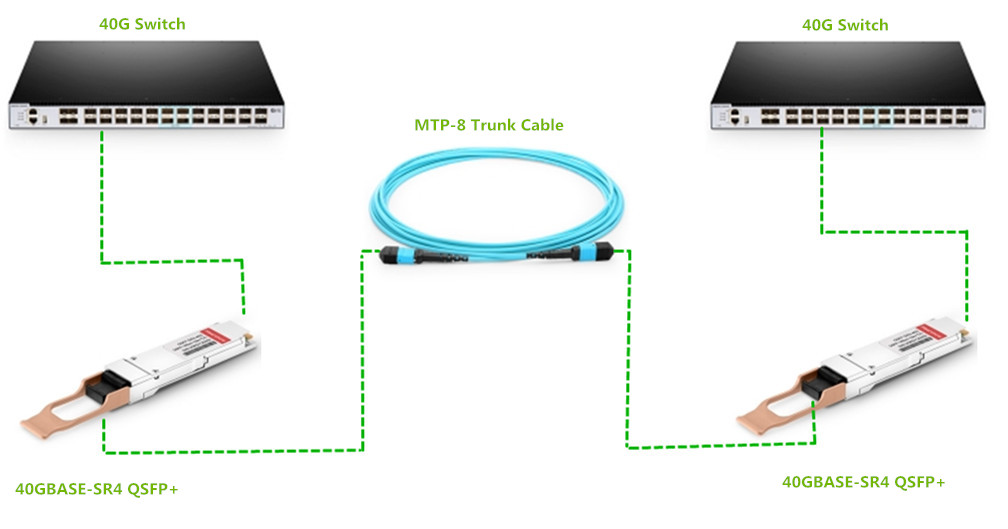
In 40G data center, the simplest way to connect two 40G switches is to use the MTP trunk cable. As the picture shows, 40G data transmission can be achieved by connecting the both ends of the MTP trunk cable with the 40G QSFP transceivers inserted into the two 40G switches.

MTP-8 solution in 40G data center 

Example 2: MTP to LC breakout cable in 10G/40G
 
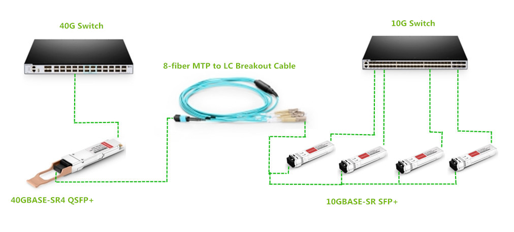
For 10G to 40G migration, using the MTP breakout cable is a simple way. As shown in the following picture, the MTP to LC breakout cable connects a 40G transceiver and four 10G transceivers. So the 40G data can be transmitted from 10G switch to 40G switch through the MTP to LC breakout cable.

8 fiber MTP-LC breakout cable in 10G/40G migration 

Example 3: MTP LC patch panel in 10G/40G
 
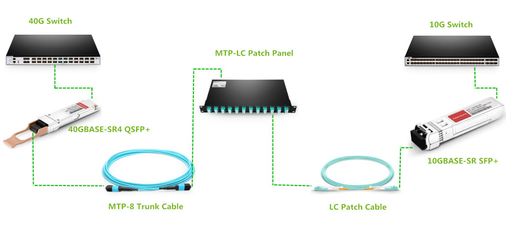
Besides using MTP breakout cable to achieve 10G to 40G migration, you can also use the MTP LC patch panel to fulfill 40G data transmission. The picture below shows the connectivity method. The 96 fibers MTP LC patch panel acts as a middleman between 10G to 40G connection. It has twelve 8-fiber MTP adapters on the rear and twelve 8 fiber LC adapters on the front. The MTP LC patch panel connects 40G QSFP ports with MTP trunk cable to the back of patch panel and then breaks out as 48 x 10G on the front with LC patch cords.

MTP-8 to LC patch panel in 10G/40G migration 

Summary
 
Supporting the current and future 8-fiber applications, MTP-8 is considered as the most efficient and the most future-proof connectivity solution. Anyone with a near-tern migration plan to adopt 40G or 100G in the data center will find great benefits in adopting MTP-8 connectivity solution. In all, MTP-8 solution can ensure data centers have the most cost-effective, future-proof network available, with a easier migration path that scales out to 400G transmission.

2017年2月24日星期五

Introduction to MPO Connector

Introduced several years ago, MPO connectors are now widely used around the world. They are designed to reduce the amount of time required for fusion splicing individual connectors. Combining lots of fibers in one connector, the MPO connector not only greatly reduces the time of connecting fibers, but also saves a lot of space. This post will introduce the detailed information about MPO connector.

MPO Connector Appearance
 
Each MPO connector has a key on one side of the connector body. When the key sits on the top, this is referred to as the key up position. When the key sits on the bottom, this is called key down. In this orientation, each of the fiber holes in the connector is numbered in sequence from left to right. We refer to these connector holes as positions, or P1, P2, etc. Moreover, each connector is additionally marked with a white dot on the connector body to designate the position 1 side of the connector when it is plugged in.

MPO connector 

MPO Connector Types
 
MPO connector is originally designed for ribbon fiber and available in 12, 24, 48 and 72 fiber variants. Generally, there are two popular MPO connector types: 12-fiber MPO connector and 24-fiber MPO connector.

12-Fiber MPO Connector
 
A 12-fiber MPO connector can deliver 6x10G transmit fibers and 6x10G receive fibers. The transceivers and the equipment were only capable of supporting 40G data rates, so here we have a dilemma. We have a 12-fiber MPO connector that can deliver 60G but is actually only delivering 40G. This means that 33% of the connectors fibers were not being used. Actually 8 fibers were being used at the transceiver and 4 were just spares. The 12-fiber MPO connector was not the best backbone choice in the long term as no one could really foresee how the industry would evolve.

12-fiber MPO connector  

Accommodating 12 fibers, the 12-fiber MPO connector provides up to 12 times the density, thereby offering savings in rack space. It is the first connector having enough repeatable performance to be accepted in data centers. If you build a backbone with a 12-fiber MPO connector, basically you can put any connection on the end to be future proofed (LC, SC, etc.). Thus most of data centers are built with 12-fiber MPO cabling in the backbone and MPO-LC harnesses connecting to equipment like switches and servers. Many equipment today still has an LC transceiver interface, therefore the harness is required to convert from MPO in the backbone to LC at the port.

24-Fiber MPO Connector
 
The companies that promoted the 12-fiber MPO connector suddenly realized that it no longer matched the requirements of the data center. Every equipment coming into the data center was either 40G (8 fibers) or 100G (24 fibers). 12 is not divisible by 8, but 24 is. If you combine 2x12 fiber MPO connectors in the backbone, you can connect 3x8 fiber MPO connectors with zero fiber wasteage at the switch. The 24-fiber MPO connector has similar performance to the 12 if not exactly the same.

24-fiber MPO connector 

The 24-fiber MPO connector has two rows of 12 fibers. And this additional row of fibers requires an increase in the spring force to push all of those fibers together, actually double what you need for 12. With the same size as a 12-fiber MPO connector, the 24-fiber MPO connector has double the amount of fibers and reduces the amount of cable required at the back end because a 24 fiber cable is only marginally bigger than a 12 fiber cable. Moreover, why combine 2x12 fiber MPO connectors to make 3x8 when you can just have 1x24 fiber MPO connector converting to 3x8? The 24-fiber MPO connector can also satisfy the demand for 100G data rates over a single connector. 20 fibers are required for 100G (10x transmit and 10x receive).

Summary
 
MPO connector delivers the optical, mechanical and environmental performance that service providers need to expedite the addition of fiber capacity and to support higher data-rate services. It plays an important role in the high-density cabling solutions. Buy quality MPO connector, MPO cables and MPO cassettes from FS.COM to deploy your network. For more details, please visit www.fs.com or contact us over sales@fs.com.


Related Posts:

 
12-Fiber or 24-Fiber MTP/MPO Cabling: Which Is Better for 40G/100G Network?

2017年2月15日星期三

100G Transceivers: CFP/CFP2/CFP4 and QSFP28

With bandwidth demands keep growing, network service providers are looking at 40G or 100G to accommodate the constant traffic surge. For 40G QSFP+ transceivers, they are interfaced with MTP/MPO or LC connectors, which has been introduced in a previous post: 40G Transceivers With MTP/MPO Interface vs. 40G Transceivers With LC Interface. So this article will introduce 100G transceivers (CFP/CFP2/CFP4/QSFP28) which have different interface types.

100G Transceivers Standards
The 100G optical transceiver market is fragmented by many different implementations. Besides the IEEE standards, there are also 100G transceivers defined by MSA. The following table lists part of the 100G standards.

100G transceivers standards 

From the table above, we can see that there are three different interface types for 100G transceivers—24-fiber MPO, 12-fiber MPO and LC duplex. The 100G transceiver with 24-fiber MPO interface uses 20 fibers to transmit data, with 10 lanes at 10 Gbps per lane (10 transmit and 10 receive). The 100G transceivers with 12-fiber MPO interface use 8 fibers to transmit, with 4 lanes at 25 Gbps per lane (4 transmit and 4 receive). This interface standard has been introduced alongside the 100G QSFP28 transceivers to make 40G to 100G upgrade as seamless as possible. And the 100G transceivers with LC interface work over single-mode fiber cables for long-distance transmission.

100G Transceivers Types
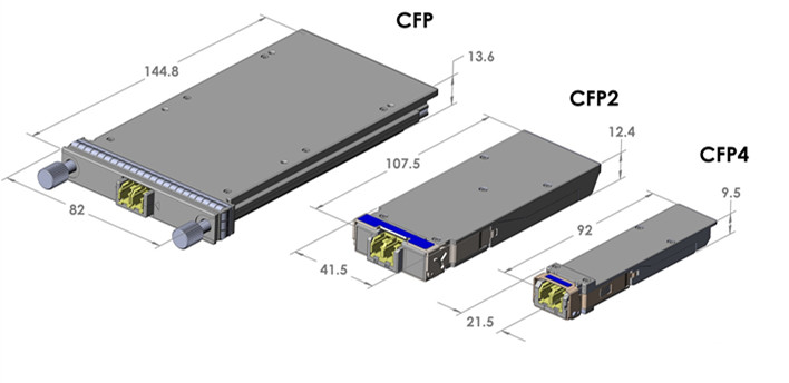
After knowing about the 100G transceivers standards, let’s move to the 100G transceivers types. There are 100G CFP/CFP2/CFP4 and QSFP28 transceivers. CFP was designed after SFP, but is significantly larger to support 100 Gbps. The electrical connection of a CFP uses 10 x 10Gbps lanes in each direction (RX, TX). The optical connection can support both 10 x 10Gbps and 4 x 25Gbps variants. With improvement in higher performance and higher density, CFP2 and CFP4 appeared. While electrical similar, they specify a form factor of 1/2 and 1/4 respectively in size of CFP. CFP, CFP2 and CFP4 modules are not interchangeable, but would be inter-operable at the optical interface with appropriate connectors.

100G transceivers: CFP, CFP2, CFP4 

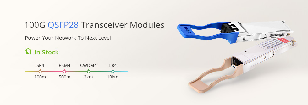
The 100G QSFP28 transceivers offer 4 independent transmit and receive channels, each capable of 25Gbps operation for an aggregate data rate of 100 Gbps. Among the various 100G transceivers, most of switch vendors choose the QSFP28 transceivers, because they make deploying 100G networks as easy as 10G networks, increasing density, decreasing power consumption and decreasing your price per bit. It’s also notable that the QSFP28 has the same physical size as the QSFP+ commonly used for 40G traffic. This means that switch vendors can increase the traffic throughput by a factor 2.5 without the need to redesign the front panel of their switches.

 100G QSFP28 transceivers
Conclusion
100G transceivers are boosting greatly for ever. Buying 100G transceivers is imminent. Choose a reliable supplier and buy the quality 100G transceivers right now. FS.COM has completed the inventory for 100G transceivers and you can enjoy the same-day shipping. We highly recommend the 100GBASE-PSM4 QSFP28 transceiver and 100GBASE-CWDM4 QSFP28 transceiver, which are affordable and can meet most of your network demands. For more details about our 100G transceivers, please visit www.fs.com.

2017年2月7日星期二

Four Types of 100G QSFP28 Transceivers Overview

For 100G optical transceivers, there are a number of form factors including CFP/CFP2/CFP4, CXP and QSFP28. Among these different 100G form factors, it appears that the market has chosen QSFP28 as the primary form factor for 100G links. Hence, this post will focus on several types of 100G QSFP28 transceivers—100GBASE-SR4 QSFP28 transceiver, 100GBASE-PSM4 QSFP28 transceiver, 100GBASE-LR4 QSFP28 transceiver, and 100GBASE-CWDM4 QSFP28 transceiver.

100GBASE-SR4 QSFP28 Transceiver
 
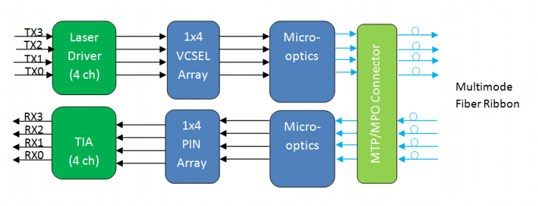
The 100GBASE-SR4 QSFP28 transceiver is a parallel 100G optical transceiver. It provides increased port density and total system cost savings. The QSFP28 full-duplex optical transceiver offers 4 independent transmit and receive channels, each capable of 25 Gbps operation for an aggregate data rate of 100 Gbps on 100 meters over OM4 MMF. Generally, 100GBASE-SR4 QSFP28 transceiver converts parallel electrical input signals into parallel optical signals by a driven VCSEL array. The transmitter module accepts electrical input signals compatible with CML (common mode logic) levels. All input data signals are differential and internally terminated. The receiver module converts parallel optical input signals via a photo detector array into parallel electrical output signals. The receiver module outputs electrical signals are also voltage compatible with CML levels. All data signals are differential and support a data rates up to 25 Gbps per channel.

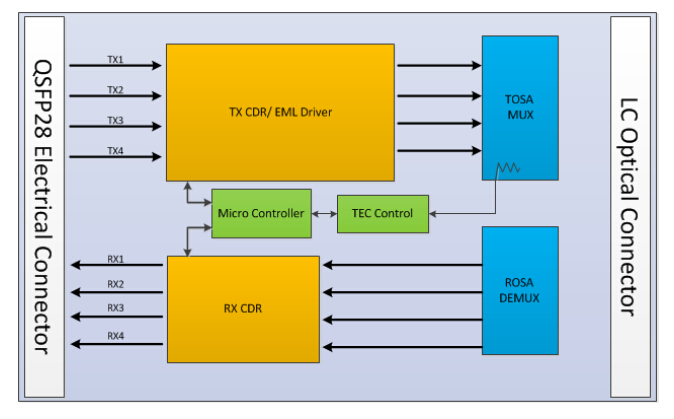
100GBASE-SR4 QSFP28 Transceiver diagram
 
100GBASE-PSM4 QSFP28 Transceiver
 
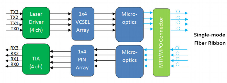
The 100GBASE-PSM4 QSFP28 transceiver is a parallel 100G single-mode optical transceiver with an MTP/MPO fiber ribbon connector. It uses 8 fibers (4 transmit and 4 receive), each transmitting at 25 Gbps, resulting in an aggregate data rate of 100 Gbps on 500 meters over SMF. The working principle of 100GBASE-PSM4 QSFP28 transceiver is nearly the same with the 100GBASE-SR4 QSFP28 transceiver. The only difference is that PSM4 works over SMF, while SR4 works over OM4 MMF.

100GBASE-PSM4 QSFP28 Transceiver diagram
 
100GBASE-LR4 QSFP28 Transceiver
 
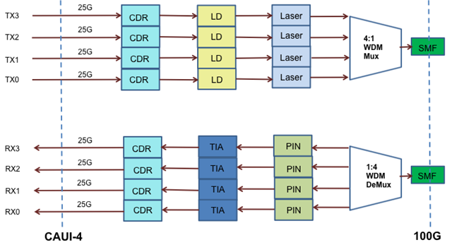
The 100GBASE-LR4 QSFP28 transceiver converts 4 input channels of 25 Gbps electrical data to 4 channels of LAN WDM optical signals and then multiplexes them into a single channel for 100G optical transmission. On the receiver side, the module demultiplexes a 100G optical input into 4 channels of LAN WDM optical signals and then converts them to 4 output channels of electrical data. The central wavelengths of the 4 LAN WDM channels are 1295.56, 1300.05, 1304.58 and 1309.14 nm as members of the LAN WDM wavelength grid defined in IEEE 802.3ba. The 100GBASE-LR4 QSFP28 transceiver provides superior performance for 100G applications up to 10 km over SMF and compliant to optical interface with IEEE802.3ba 100GBASE-LR4 requirements.

100GBASE-LR4 QSFP28 Transceiver diagram
 
100GBASE-CWDM4 QSFP28 Transceiver
 
The 100GBASE-CWDM4 QSFP28 transceiver is a full duplex optical transceiver that provides a high-speed link at aggregated data rate of 100 Gbps over 2 km on SMF. The transmitter path converts four lanes of serial electrical data to optical signal. The optical signals from the four lasers are optically multiplexed and coupled to single-mode fiber through an industry standard LC optical connector. The optical signals are engineered to meet the CWDM4 MSA specifications. On the receive side, the four incoming wavelengths are separated by an optical demultiplexer into four separated channels.

100GBASE-CWDM4 QSFP28 Transceiver diagram
 
Summary
 
This article has introduced the basic information about 100GBASE-SR4 QSFP28 transceiver, 100GBASE-PSM4 QSFP28 transceiver, 100GBASE-LR4 QSFP28 transceiver, and 100GBASE-CWDM4 QSFP28 transceiver. The following table summarizes the differences of these four types of 100G QSFP28 transceivers. You should first make clear each type and then choose the one that best suits your network demands. In addition to the generic ones mentioned in this post, we also have other 100G QSFP28 transceivers compatible with major brands such as Cisco, etc. For the detailed information, you can visit www.fs.com.

Transceiver TypeInterfaceTransmission Distance
100GBASE-SR4 QSFP28 TransceiverMTP/MPO-12100m over 8 MMFs
100GBASE-PSM4 QSFP28 TransceiverMTP/MPO-12500m over 8 SMFs
100GBASE-LR4 QSFP28 TransceiverLC duplex10km over 2 SMFs
100GBASE-CWDM4 QSFP28 TransceiverLC duplex2km over 2 SMFs

Related Article: QSFP28 – A Better Way to 100G

Originally published: www.fiberopticshare.com/100g-qsfp28-transceivers-overview.html

2017年2月4日星期六

How to Set up Wireless Network?

A wireless network is completely wireless, which means that any device with a WiFi networking card installed will be able to access the Internet provided you have the right password. Wireless networks are surely convenient for the daily life. This post tells about the things you should consider before building the wireless network, and then list the procedures of setting up wireless network.

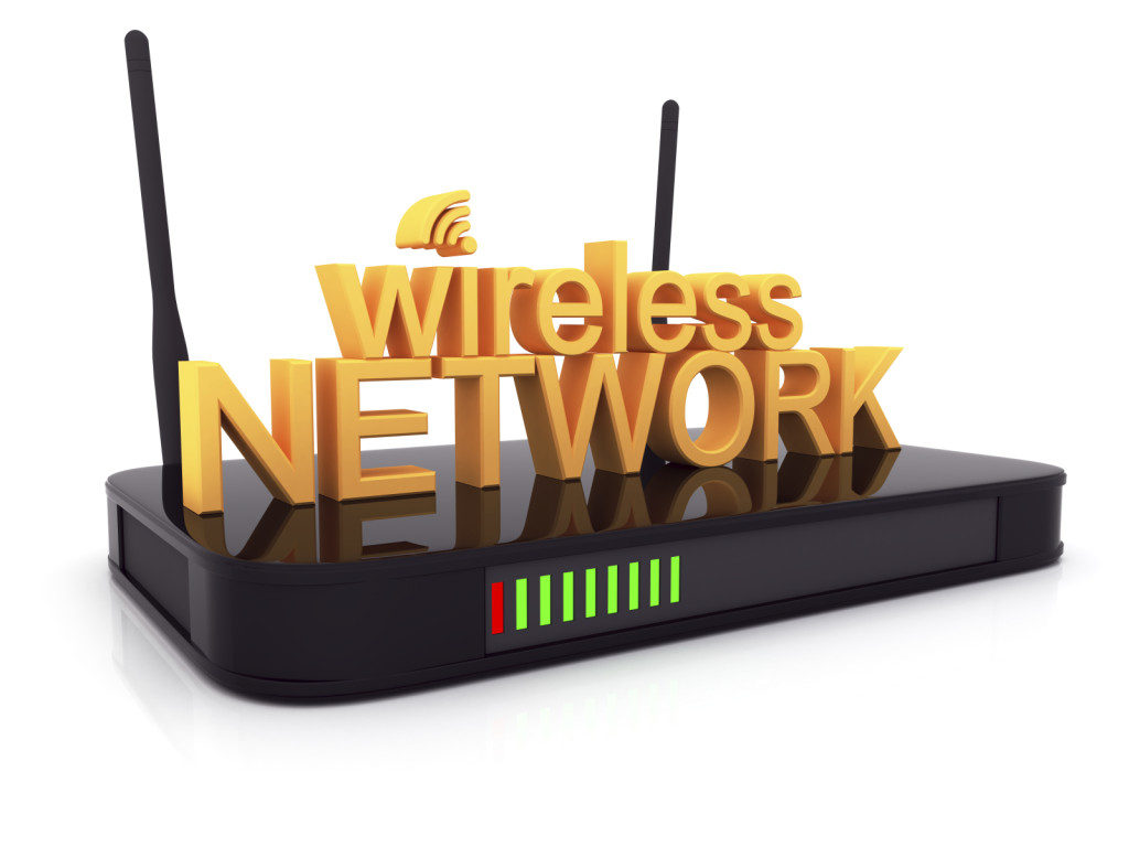
wireless network 

Things to Consider Before Taking Action
 
Before building your own wireless network, you should make clear the following points.

First, what you are going to use the wireless network for. Make sure you determine this ahead of time so that you can decide how much speed and coverage you will need. Obviously, the more you want to do with your wireless network, the faster it will need to be. Remember that the more devices you connect to your network, the more speed is divided among them. Too many devices will significantly lower network performance.

Second, confirm how much coverage you will need for your wireless network. If the house is too big, you may need to install more than one access point, which will require configuration. Keep in mind that the construction of the house can affect the coverage of your wireless network. Some walls are made of extra thick concrete that will reduce coverage in your network.

Last, determine where you will place your wireless access point. To get maximum coverage, it’s best to place it in a location that is elevated and away from sources of interference. You can also put the access point near the center of the area where you’ll be operating the majority of your wireless equipment. Keep in mind that your neighbors’ wireless networks may interfere with yours, and vice versa, if theirs is installed with the default channel settings.

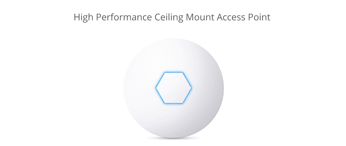
wireless access point 

How to Set up Wireless Network?
 
All you need for a wireless network is a wireless router, a computer or laptop with wireless capabilities, a modem and two Ethernet cables. Follow the instructions below to setup your wireless network.

1. Find the best location for your wireless router.

2. Turn off the modem. Power off the cable or DSL modem from your ISP before connecting your equipment.

3. Connect the router to the modem. Plug an Ethernet cable into the router’s WAN port and then the other end to the modem.

4. Connect your laptop or computer to the router. Plug one end of another Ethernet cable into the router’s LAN port and the other end into your laptop’s Ethernet port.

5. Power up the modem, router, and computer in turn.

6. Go to the management web page for your router. Open a browser and type in the IP address of the router's administration page.

7. Change the default administrator user name and password for your router. This setting is usually found in a tab or section called administration. Remember to use a strong password that you won't forget.

8. Add WPA2 security. This step is essential. You can find this setting in the wireless security section, where you'll select which type of encryption to use and then enter a passphrase of at least 8 characters—the more characters and the more complex the password, the better.

9. Change the wireless network name (SSID). To make it easy for you to identify your network, choose a descriptive name for your SSID (Service Set Identifier) in the wireless network information section.

10. Change the wireless channel. If you’re in an area with a lot of other wireless networks, you can minimize interference by changing your router's wireless channel to one less used by other networks. You can use a WiFi analyzer app for your smartphone to find the least crowded channel or just use trial and error (try channels 1, 6, or 11, since they don't overlap).

11. Set up the wireless adapter on the computer. After saving the configuration settings on the router above, you can unplug the cable connecting your computer to the router. Then plug your USB or PC card wireless adapter into your laptop, if it doesn't already have a wireless adapter installed or built-in. Your computer may automatically install the drivers or you may have to use the setup CD that came with the adapter to install it.

12. Finally, connect to your new wireless network. On your computer and other wireless-enabled devices, find the new network you set up and connect to it.

Summary
 
After reading this post, have you understood how to set up wireless network? To maximize the WiFi performance, you should confirm the coverage and find the best place for the wireless access point. And then set up the wireless network step by step. We provide a series of solutions for wireless access service. For more details, please visit www.fs.com.


PON Fault Scenarios and Troubleshooting Basics

A PON network consists of an OLT connected via a PON splitter to multiple ONTs (one for each subscriber, up to 64 subscribers). Sometimes, a second splitter can be connected in cascade to the first splitter to dispatch services to buildings or residential areas, which has been introduced more clearly in the previous post “Understanding the Split Ratios and Splitting Level of Optical Splitters”. This post will tell about troubleshooting of a point-to-multipoint FTTH network, also defined as a PON network.

simple PON architecture with one splitter
cascaded PON architecture with more than one splitter

PON Fault Scenarios
Scenario 1: Simple PON (only one customer is affected)

There are three potential faults when only one subscriber cannot receive service—fault in the distribution fiber between the customer and the closest splitter, or fault in the ONT equipment, or fault in the customer’s home wiring.

PON fault scenario
PON fault scenario

Scenario 2: Cascaded PON (all affected customers are connected to the same splitter)

When all customers connected to the same splitter cannot receive service, but others connected to the same OLT can, the cause may be one of the two—fault at the last splitter, or fault in the fiber link between the cascaded splitters.

PON fault scenario

Scenario 3: All customers are affected (at the OLT level)

Whether or not the PON is cascaded, all customers dependent on the same OLT may be affected. If all customers are affected, the cause may be from of the three—fault in the splitter closest to the OLT, or fault in the feeder fiber cable of the network, or fault in the OLT equipment.

PON fault scenario

PON Troubleshooting Basics
Troubleshooting a PON first involves locating and identifying the source of an optical problem. The following picture offers a complete view of all of the possible fault locations depending on how many customers are affected, and the best location to shoot an OTDR.

PON troubleshooting

Generally, most PON problems can be located using PON power meter and PON-optimized OTDR. The power meter is connected as a pass-through device, allowing both downstream and upstream traffic to travel unimpeded. It measures the power at each wavelength simultaneously and can be used for troubleshooting at any point in the network. A monitoring OTDR provides a graphical trace that enables to locate and characterize every element in a link, including connectors, splices, splitters, couplers and faults. OTDRs designed specifically for in-service PON troubleshooting exist. These OTDRs feature a dedicated port for testing at 1625 or 1650 nm and incorporate a filter that rejects all unwanted signals (1310, 1490 and 1550 nm) that could contaminate the OTDR measurement. Only the OTDR signal at 1625 or 1650 nm is allowed to pass through the filter, generating a precise OTDR measurement. In-service OTDR troubleshooting of optical fiber should be done in a way that does not interfere with the normal operation and expected performance of the information channels. Testing with the 1625 or 1650nm wavelength does just that. A PON-optimized OTDR does not interfere with the CO’s transmitter lasers because the 1650nm wavelength complies with the ITU-T L.41 Recommendation. The addition of a broadband filter, acting as a 1625 or 1650nm testing port at the CO’s WDM coupler, may be beneficial. And the quality of service provided to other subscribers serviced by the same 1xN splitter is not affected. Consequently, the technician can connect the OTDR’s 1625 or 1650nm port to the ONT and send the signal toward the CO. If a 1625 or 1650nm testing port is added to the CO, it is also possible to perform tests from the CO down to the ONT, but a 1625 or 1650nm filter may be needed at each ONT.

Summary
PON troubleshooting should first find the fault locations of the network. This post lists three types of potential fault scenarios for your reference. After knowing where the fault is, then you should use the correct tools to test and verify. PON power meter and OTDR can help significantly during the testing process. If you are confused about PON troubleshooting, hope the information in this post will be helpful.