显示标签为“PON splitter”的博文。显示所有博文

2017年2月4日星期六

PON Fault Scenarios and Troubleshooting Basics

A PON network consists of an OLT connected via a PON splitter to multiple ONTs (one for each subscriber, up to 64 subscribers). Sometimes, a second splitter can be connected in cascade to the first splitter to dispatch services to buildings or residential areas, which has been introduced more clearly in the previous post “Understanding the Split Ratios and Splitting Level of Optical Splitters”. This post will tell about troubleshooting of a point-to-multipoint FTTH network, also defined as a PON network.

simple PON architecture with one splitter
cascaded PON architecture with more than one splitter

PON Fault Scenarios
Scenario 1: Simple PON (only one customer is affected)

There are three potential faults when only one subscriber cannot receive service—fault in the distribution fiber between the customer and the closest splitter, or fault in the ONT equipment, or fault in the customer’s home wiring.

PON fault scenario
PON fault scenario

Scenario 2: Cascaded PON (all affected customers are connected to the same splitter)

When all customers connected to the same splitter cannot receive service, but others connected to the same OLT can, the cause may be one of the two—fault at the last splitter, or fault in the fiber link between the cascaded splitters.

PON fault scenario

Scenario 3: All customers are affected (at the OLT level)

Whether or not the PON is cascaded, all customers dependent on the same OLT may be affected. If all customers are affected, the cause may be from of the three—fault in the splitter closest to the OLT, or fault in the feeder fiber cable of the network, or fault in the OLT equipment.

PON fault scenario

PON Troubleshooting Basics
Troubleshooting a PON first involves locating and identifying the source of an optical problem. The following picture offers a complete view of all of the possible fault locations depending on how many customers are affected, and the best location to shoot an OTDR.
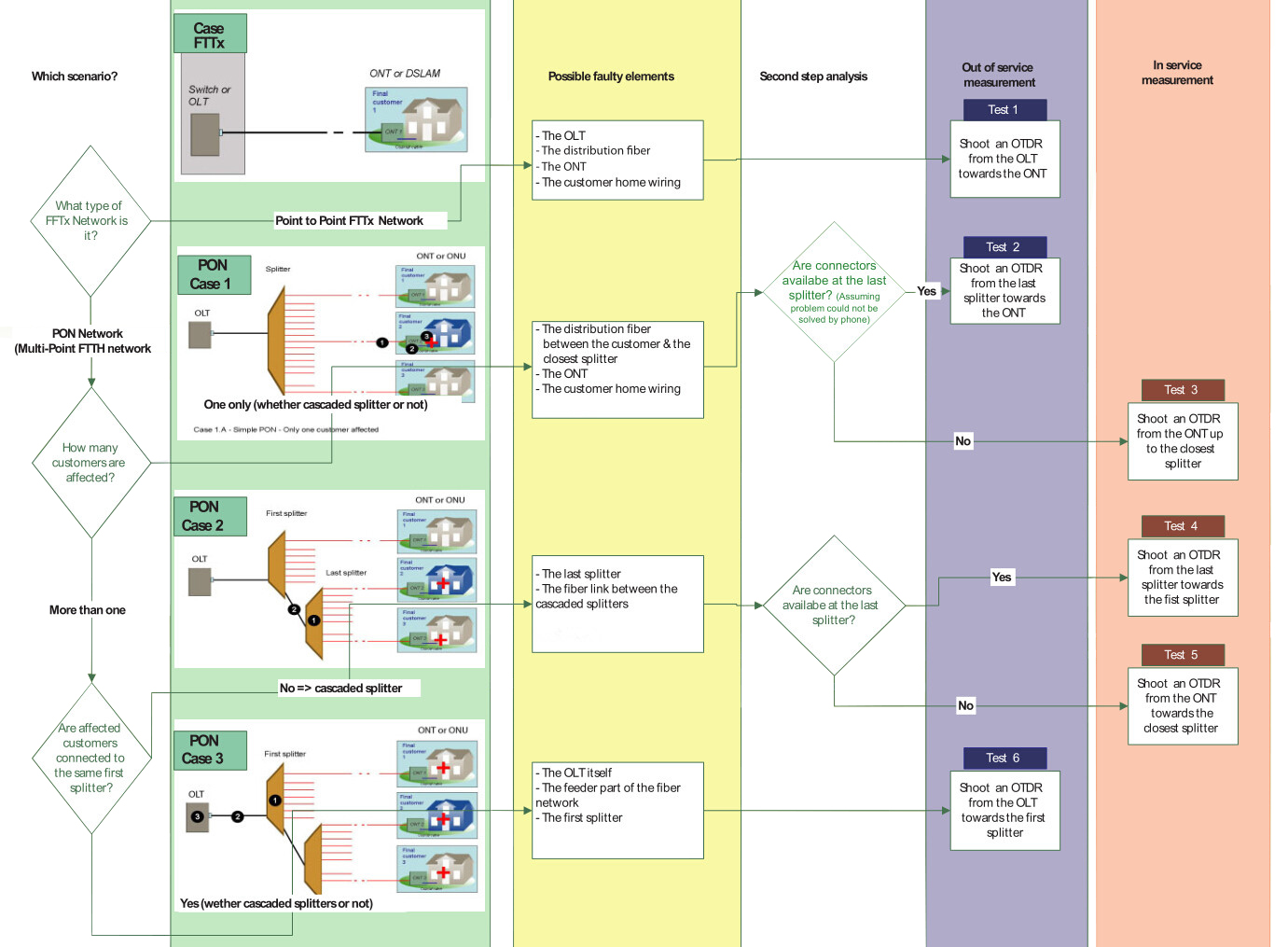
PON troubleshooting

Generally, most PON problems can be located using PON power meter and PON-optimized OTDR. The power meter is connected as a pass-through device, allowing both downstream and upstream traffic to travel unimpeded. It measures the power at each wavelength simultaneously and can be used for troubleshooting at any point in the network. A monitoring OTDR provides a graphical trace that enables to locate and characterize every element in a link, including connectors, splices, splitters, couplers and faults. OTDRs designed specifically for in-service PON troubleshooting exist. These OTDRs feature a dedicated port for testing at 1625 or 1650 nm and incorporate a filter that rejects all unwanted signals (1310, 1490 and 1550 nm) that could contaminate the OTDR measurement. Only the OTDR signal at 1625 or 1650 nm is allowed to pass through the filter, generating a precise OTDR measurement. In-service OTDR troubleshooting of optical fiber should be done in a way that does not interfere with the normal operation and expected performance of the information channels. Testing with the 1625 or 1650nm wavelength does just that. A PON-optimized OTDR does not interfere with the CO’s transmitter lasers because the 1650nm wavelength complies with the ITU-T L.41 Recommendation. The addition of a broadband filter, acting as a 1625 or 1650nm testing port at the CO’s WDM coupler, may be beneficial. And the quality of service provided to other subscribers serviced by the same 1xN splitter is not affected. Consequently, the technician can connect the OTDR’s 1625 or 1650nm port to the ONT and send the signal toward the CO. If a 1625 or 1650nm testing port is added to the CO, it is also possible to perform tests from the CO down to the ONT, but a 1625 or 1650nm filter may be needed at each ONT.

Summary
PON troubleshooting should first find the fault locations of the network. This post lists three types of potential fault scenarios for your reference. After knowing where the fault is, then you should use the correct tools to test and verify. PON power meter and OTDR can help significantly during the testing process. If you are confused about PON troubleshooting, hope the information in this post will be helpful.

2015年12月16日星期三

Introduction to PON Technologies

Passive optical network (PON) is a very significant class of fiber access system in the world and it enjoys a dominant position in the access market. GPON and EPON are the two classifications of PON. The primary differences between the GPON and EPON lie in the protocols used for upstream and downstream communications. This article will introduce PON, GPON and EPON sequentially.

Passive Optical Networks (PON)
 
A PON is a fiber network that only uses fiber and passive components like PON splitters and combiners rather than active components like amplifiers, repeaters, or shaping circuits. Thus PON network costs significantly less than those using active components, but it has a shorter range of coverage limited by signal strength. An active optical network (AON) is able to cover a range to about 100 km (62 miles), while a PON is typically limited to fiber cable runs of up to 20 km (12 miles). PON is also called FTTH (fiber to the home) network.

The typical PON arrangement is a point to multi-point (P2MP) network where a central optical line terminal (OLT) at the service provider’s facility distributes TV or Internet service to as many as 16 to 128 customers per fiber line. Dividing a single optical signal into multiple equal but lower-power signals, the optical splitters distribute the signals to users. An ONU (optical network unit) terminates the PON at the customer’s home. Usually, ONU communicates with ONT (optical network terminal). The ONU/ONT may be one device.

Gigabit Passive Optical Networks (GPON)
 
GPON utilizes optical wavelength division multiplexing (WDM) so a single fiber could be used for both upstream and downstream data. A laser on a wavelength of 1490 nm transmits downstream data, while upstream data transmits on a wavelength of 1310 nm.

While each ONU gets the full downstream rate of 2.488 Gbits/s, GPON uses a time division multiple access (TDMA) format to allocate a specific timeslot to each user. It divides the bandwidth, so each user gets a fraction such as 100 Mbits/s depending on the way the service provider allocates it. The upstream rate is less than the maximum as it is shared with other ONUs in a TDMA scheme. The distance and time delay of each subscriber are determined by the OLT. Then software provides a way to allot timeslots to upstream data for each user. The typical split of a single fiber is 1:32 or 1:64, which means each fiber can serve up to 32 or 64 subscribers. Split ratios up to 1:128 are possible in some systems.

Ethernet Passive Optical Networks (EPON)
 
Based on the Ethernet standard 802.3, EPON 802.3ah specifies a similar passive optical network with a range up to 20 km. EPON uses WDM with the same optical frequencies as GPON and TDMA. The raw line data rate is 1.25 Gbits/s in both the upstream and downstream directions.

EPON technology provides bidirectional 1Gb/s links using 1490nm wavelength for downstream and 1310nm wavelength for upstream, with 1550nm wavelength reserved for future extensions or additional services. EPON is fully compatible with other Ethernet standards, so no encapsulation or conversion is necessary when connecting to Ethernet-based networks on either end. The same Ethernet frame is used with a payload for up to 1518 bytes. As Ethernet is the primary networking technology utilized in local area networks (LAN) and now in metro area networks (MAN), no protocol conversion is needed.

Summary
 
PONs are used to provide triple-play services including TV, and Internet service to subscribers. The lower cost of passive components means simpler systems with fewer components failing or requiring maintenance. The primary disadvantage is shorter range possible, commonly no more than 12 miles or 20 kilometers. As the demand for faster Internet service and more video grows, PONs are growing in popularity. The age of PON has begun. It is a new era of access network upon us.

Article source: www.fiberopticshare.com/introduction-to-pon-technologies.html