显示标签为“OTDR”的博文。显示所有博文

2017年2月4日星期六

PON Fault Scenarios and Troubleshooting Basics

A PON network consists of an OLT connected via a PON splitter to multiple ONTs (one for each subscriber, up to 64 subscribers). Sometimes, a second splitter can be connected in cascade to the first splitter to dispatch services to buildings or residential areas, which has been introduced more clearly in the previous post “Understanding the Split Ratios and Splitting Level of Optical Splitters”. This post will tell about troubleshooting of a point-to-multipoint FTTH network, also defined as a PON network.

simple PON architecture with one splitter
cascaded PON architecture with more than one splitter

PON Fault Scenarios
Scenario 1: Simple PON (only one customer is affected)

There are three potential faults when only one subscriber cannot receive service—fault in the distribution fiber between the customer and the closest splitter, or fault in the ONT equipment, or fault in the customer’s home wiring.

PON fault scenario
PON fault scenario

Scenario 2: Cascaded PON (all affected customers are connected to the same splitter)

When all customers connected to the same splitter cannot receive service, but others connected to the same OLT can, the cause may be one of the two—fault at the last splitter, or fault in the fiber link between the cascaded splitters.

PON fault scenario

Scenario 3: All customers are affected (at the OLT level)

Whether or not the PON is cascaded, all customers dependent on the same OLT may be affected. If all customers are affected, the cause may be from of the three—fault in the splitter closest to the OLT, or fault in the feeder fiber cable of the network, or fault in the OLT equipment.

PON fault scenario

PON Troubleshooting Basics
Troubleshooting a PON first involves locating and identifying the source of an optical problem. The following picture offers a complete view of all of the possible fault locations depending on how many customers are affected, and the best location to shoot an OTDR.
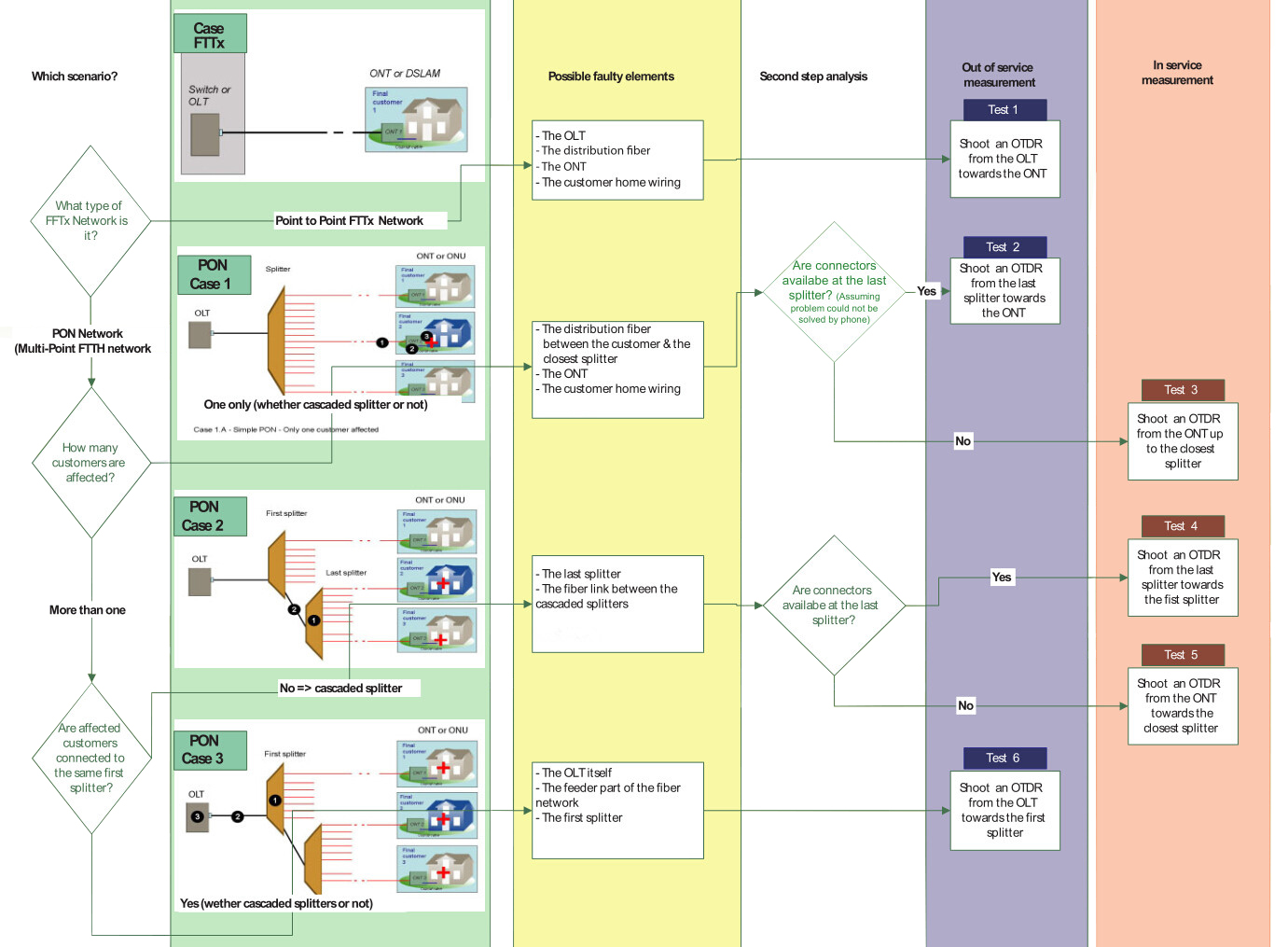
PON troubleshooting

Generally, most PON problems can be located using PON power meter and PON-optimized OTDR. The power meter is connected as a pass-through device, allowing both downstream and upstream traffic to travel unimpeded. It measures the power at each wavelength simultaneously and can be used for troubleshooting at any point in the network. A monitoring OTDR provides a graphical trace that enables to locate and characterize every element in a link, including connectors, splices, splitters, couplers and faults. OTDRs designed specifically for in-service PON troubleshooting exist. These OTDRs feature a dedicated port for testing at 1625 or 1650 nm and incorporate a filter that rejects all unwanted signals (1310, 1490 and 1550 nm) that could contaminate the OTDR measurement. Only the OTDR signal at 1625 or 1650 nm is allowed to pass through the filter, generating a precise OTDR measurement. In-service OTDR troubleshooting of optical fiber should be done in a way that does not interfere with the normal operation and expected performance of the information channels. Testing with the 1625 or 1650nm wavelength does just that. A PON-optimized OTDR does not interfere with the CO’s transmitter lasers because the 1650nm wavelength complies with the ITU-T L.41 Recommendation. The addition of a broadband filter, acting as a 1625 or 1650nm testing port at the CO’s WDM coupler, may be beneficial. And the quality of service provided to other subscribers serviced by the same 1xN splitter is not affected. Consequently, the technician can connect the OTDR’s 1625 or 1650nm port to the ONT and send the signal toward the CO. If a 1625 or 1650nm testing port is added to the CO, it is also possible to perform tests from the CO down to the ONT, but a 1625 or 1650nm filter may be needed at each ONT.

Summary
PON troubleshooting should first find the fault locations of the network. This post lists three types of potential fault scenarios for your reference. After knowing where the fault is, then you should use the correct tools to test and verify. PON power meter and OTDR can help significantly during the testing process. If you are confused about PON troubleshooting, hope the information in this post will be helpful.

2016年1月4日星期一

How Much Do You Know About FTTH PON Testing?

Passive optical network (PON) is a cost-effective way to deliver high-bandwidth broadband services to users and widely deployed all over the world. FTTH uses PON technology and provides high bandwidth from the central office (CO) to subscribers. FTTH PON system achieves network reliability and makes network testing, monitoring and measuring easier. This article will tell about FTTH PON testing from the four aspects below.

Connector Inspection

Connector inspection/cleaning plays an important role in network installation and maintenance. Typically an optical microscope is used for connector inspection. To prevent accidental eye damage when inspecting fibers potentially carrying live traffic, a video microscope images the connector end-face and displays the magnified image on a handheld display. In this way, the dirt, debris or damage on the connector could be easily detected. According to the study by NTT-Advanced Technology, connector contamination and damage are the key reason for poor optical network performance.

Insertion Loss Test

In telecommunications, the term “insertion loss” expressed in dB, refers to the loss of signal power resulting from the insertion of a device in a transmission line or in an optical fiber. An insertion loss test measures the end-to-end loss of the installed link by injecting light with a known power level and wavelength at one end, and then measures the received power level output from the other end. The measured difference between the transmitted and received power levels exactly indicates the very optical loss through the network. In some occasions, insertion loss is allowed and considered acceptable when the measured loss level is lower than the budget loss level.

Optical Return Loss Test

In telecommunications, return loss expressed in dB, means the loss of power in the signal returned or reflected by a discontinuity in a transmission line which can be a mismatch with the terminating load or with a device inserted in the line. The optical return loss test injects light with known wavelength and power level into one end and measures the power level returned to that same end. Then the return loss is the difference between the injected power level and the measured return level. When the return loss is higher than the budgeted return loss target, it is considered acceptable.

Typically insertion loss test and return loss test are performed by using wavelengths at those which will be used during network operation. For FTTH PON system, 1310nm wavelength is used in the upstream direction, while 1490nm and 1550nm wavelengths are used in the downstream direction. So it is essential to have insertion and return loss testing at 1310nm, 1490nm and 1550nm wavelengths. The optical network is considered ready for activation when the insertion loss and return loss measured at each wavelength are within the budgeted levels for the link. However, in some cases, the network operator uses an optical time domain reflectometry (OTDR) as the following picture shows for more fully documented network.

JDSU MTS 4000 OTDR


Optical Time Domain Reflectometry (OTDR)

OTDR scans a fiber from one end to measure the length, loss and optical return loss of an optical network. And it also locates and measures reflective or non-reflective events in the network caused by splices, connectors, splitters, faults, etc. OTDR operates like a radar by injecting narrow pulses of light into the fiber under test. As each pulse travels down the fiber, imperfections in the fiber scatter some of the light, with some of this Rayleigh-scattered light being guided back up the fiber.

Summary

From the above description, four tests are commonly used to verify optical links. Proper testing is critical for FTTH PON installing, activating and maintaining, because excess loss or reflectance can result in poor network performance if not detected and corrected. And over time, transmission errors will occur before the need for any maintenance activity.

Article source: www.fiberopticshare.com/how-much-do-you-know-about-ftth-pon-testing.html

2015年10月7日星期三

OTDR, LTS and Source&Meter: Which Is Better for You?

As the technology advances further, the kinds of fiber optic testers also have increased. The variety of choices of such devices can be overwhelming to a would-be buyer. This paper will introduce you some common types, such as OTDR (optical time domain reflectometer), LTS (loss test set) and Source & Meter. But there is a problem you should know that the function of them is very similar since they all can be used to test cable installation or outside plant applications. As a result, it would be hard for us to select the right one for detecting our fiber optic events. Under this circumstances, here comes the question: OTDR, LTS and Source&Meter, which is better?

Introduction to OTDR, LTS and Source&Meter

Before you know how to choose the right one from these fiber optic testers, you must have a basic knowledge of them. So next, OTDR (optical time domain reflectometer), LTS (loss test set) and Source & Meter, each of them would be given a brief introduction.

OTDR - OTDR is essentially an optical radar. It sends pulses of light into optical fibers, and then analyzes the minuscule amounts of light which is reflected back to them. Also, complex computations are used to determine the size and distance to events encountered in the fiber run. Events are defined as losses or changes in the fiber’s light-carrying capacity.

OTDR 

LTS - In the heart of the LTS, it is the combination of a power meter and light source. Measurements are made with a two stage process. First the source power is measured, then light is put through the device to be tested, and a second measurement is made. The difference in the measurements is the device loss.

LTS

Source & Meter - Sources and Meters perform the same functions as an LTS. But compared with LTS, it has greater flexibility since a single source and meter pair can also be used at each end of a link.

Source & Meter

OTDR, LTS and Source&Meter: Which Is Better

After knowing about the basic knowledge about these fiber optic testers, there are some features of them you should know so that you can choose the right fiber optic tester for your fiber networks.

Cost - Compared to a loss test set or source & meter, OTDR requires more technical expertise which determines it has higher labor expense. What is more, it has high asset expense and administration expense. So if you plan to use an OTDR frequently, it makes sense to buy one. If not, you had better rent one to reduce cost. As to LTS and Source & Meter, one LTS may be cheaper than a source / meter pair. Because it has less inventory to maintain and deploy, that is why its ongoing costs is lower.

Ease of use - OTDR readings must be analyzed and interpreted by trained and experienced people. It’s difficult for a less qualified installer to operate an OTDR and make sense out of it. As a result, using this device can require considerable time and effort. But LTS is the simplest way to ensure that connections are up to standard, and is widely used by almost everyone involved in hands-on work. Source & Meter is slightly harder to use when compared with LTS in that it does not have some sorts of automated wavelength synchronisation.

Application - OTDR is designed for outside plant (OSP) applications. Most OSP installations involve splicing single-mode fiber to get longer runs and the OTDR allows verifying the quality of the splice. But when that link is finished, it must still be tested for insertion loss with a light source, power meter and reference cables, just like premises cables. Premises cables rarely have splices and are short, often too short for the OTDR to measure. LTS can be used to simply and reliably measure end to end loss of installed systems, preferably using a bi-directional or two-way method at multiple wavelengths, with minimum inventory and modest technician skill levels. The use of Source & Meter is more flexibility. One source & meter can measure a link, whereas two LTS (Loss Test Set) instruments are needed. And a source is not needed to do transmission power measurements, so it can be used elsewhere.

From the above analysis, we can see that the cost of OTDR is the highest, and it is more suitable for experts to use. While the cost of LTS is the lowest, and it s relatively simple to use. Source & Meter is between them. In a word, these fiber optic testers are all indispensable instruments that can illuminate problems in your optical fiber before they bring your system to its knees. Once you are familiar with the features of them, you will be prepared to choose the right one to detect and eliminate your optical fiber events.