2017年5月16日星期二

MTP/MPO Connector Cleaning: One-Click Cleaner vs. Cassette Cleaner

With data centers moving to 40G/100G, MPO fiber cables are extensively deployed. To ensure the reliable and efficient performance of the MPO cables, it is critical to clean the MPO connectors before mating to other equipment as contaminated connectors would lead to degraded performance and costly but preventable failures. There are two ways to clean MTP/MPO connectors. One is to use cassette cleaner, while the other is to use one-click cleaner. This post will talk about these two types of cleaning methods for MTP/MPO connectors.

One-Click Cleaner vs. Cassette Cleaner: Using Rules

The one-click cleaner for MTP/MPO connectors is a cost-effective tool for cleaning fiber end-faces without the use of alcohol. It can clean both exposed jumper ends and connectors in adapters with one-push action. A cassette cleaner contains a refillable lint free reel of cloth that is moved after each cleaning, always presenting a clean surface. It is applicable primarily for cleaning connectors with one-wipe action in dry cleaning without any alcohol and other harsh chemicals.

One-Click Cleaner vs. Cassette Cleaner: Cleaning Procedures

For both the two cleaning methods, please always inspect before cleaning. If the connector is already clean, there is no need to clean it.

Cleaning Procedures of One-Click Cleaner (For Connectors in Adapters)
  • Pull off the guide cap.
  • Insert the cleaning tool into the bulkhead and turn the cleaning wheel backwards until click two times.
Cleaning Procedures of One-Click Cleaner (For Exposed Connectors)
  • Carefully pull out the guide cap cover.
  • Insert the patch cord into the cleaning tool, apply slight pressure and turn the cleaning wheel backward until click two times.
one-click cleaner for MTP/MPO connectors
Cleaning Procedures of Cassette Cleaner
  • Remove connector dust cover.
  • Select the appropriate cleaner for male/female.
  • For female MTP/MPO connectors, use the cleaning brush and fluid to remove any debris from the pin holes.
  • Depress the lever so that a fresh area of cleaning cloth is exposed.
  • Position the ferrule against the cloth so that the fibers are in contact with the cleaning material. In the case of angled connectors, the ferrule will need to be adjusted accordingly.
  • Wipe the connector in the direction shown on the cassette.
  • Release the grip to seal off the cleaning cloth.
  • Let the ferrule air-dry before inspecting with a 200xmicroscope.
  • If still contaminated repeat all steps once again.
  • Ensure that the connector does not touch any hard surfaces.
use cassette cleaner to clean MTP/MPO connectors

Note: Do not move connector back and forth. Connector is to be moved in only the direction of the arrows on the cleaner.

One-Click Cleaner vs. Cassette Cleaner: Which to Choose?

From what have described above, we can summarize that one-click cleaner can be used for connectors in adapters and exposed connectors, while cassette cleaner is only applicable for exposed connectors. Moreover, the one-click cleaner is capable of cleaning ferrules with or without guide pins. But for cassette cleaner, you should choose the correct type to clean male or female connectors. In my opinion, one-click cleaner is more convenient. Among the two, which is your choice?

2017年5月10日星期三

Roles of MTP Trunk, MTP Harness, MTP Conversion Harness in 40G/100G Migration

With bandwidth demands continuing to grow, higher and higher capacity and throughput are required in the data center. And to address these needs efficiently and effectively, a strategic approach focusing on existing user expectations and future capacity requirements is wanted. MTP/MPO cable is the good choice that can meet various network requirements. This post will list the roles of different MTP/MPO cables (MTP trunk, MTP harness, MTP conversion harness) in 10G/40G/100G migration.

10G/40G/100G Migration Solutions
 
For upgrading connection data rates, several common scenarios are available with using MTP/MPO fiber cables. Following part will list these applications out for your reference.

10G to 40G: 8-Fiber MTP Harness Cable
 
One commonly used upgrade possibility beyond 10G incorporates four 10G SFP+ transceiver connections to a 40G QSFP+, which requires a 8-fiber MPO-LC harness cable. Figure 1 illustrates one side of the transmission path utilizing this MPO harness cable in conjunction with a 40G QSFP+ to aggregate four 10G SFP+ transceivers. QSFP+ transceivers on the switches yield higher port densities and throughput.

8-fiber MTP LC harness cable in 10G to 40G migration

Figure 1: 10G to 40G upgrade by using MTP/MPO LC harness cable
 
40G to 40G: 12-Fiber MTP Trunk Cable
 
MTP trunk cable incorporates interconnected banks of QSFP+ transceivers (MPO to MPO connectivity). Figure 2 illustrates the connectivity. In this connection, 12-fiber MPO trunk cables are needed to connect the transceivers. Four fibers transmit light, four receive and four unused.

12f MTP trunk cable used in 40G connection 

Figure 2: 40G to 40G connection by using MTP/MPO trunk cable with four fibers unused

40G to 40G: 2x3 MTP Conversion Harness/Module
 
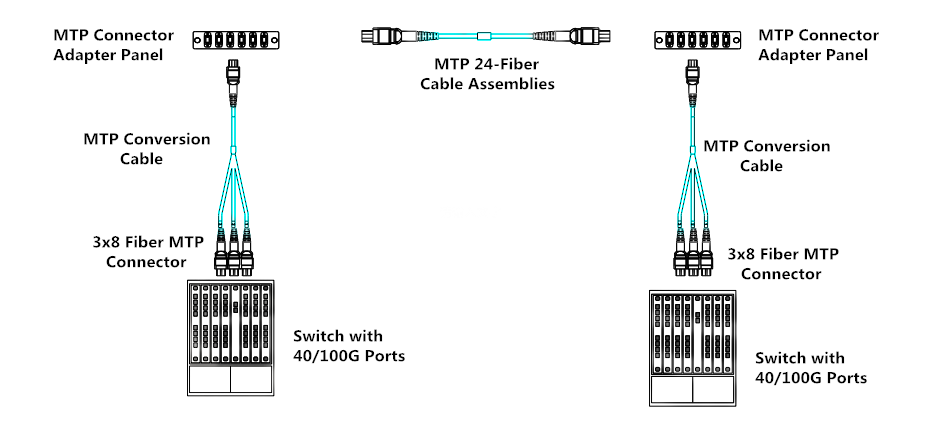
MTP conversion harness and MTP conversion module both take advantage of 100% fiber utilization. For those needing 100% fiber utilization, 2x3 MTP conversion harness or conversion module can achieve the purpose. Connectivity of the 2x3 MTP conversion harness and conversion module is the same. They are interchangeable, but must be used in pairs: one (MTP conversion harness or module) at each end of the link. Figure 3 shows an example of how MTP conversion module uses all fibers to achieve 100% fiber utilization. The eight live fibers from each of the three QSFP+ transceivers are transmitted through the trunks using the full 24 fibers. The second 2x3 conversion module unpacks these fibers to connect to the 3 QSFP+ transceivers on the other end.

MTP conversion cable/module used in 40G with 100% fiber utilization 

Figure 3: 40G to 40G connection with MTP conversion module ensuring 100% fiber utilization

100G to 100G: MTP Trunk Cable
 
For 100G to 100G connection, 24-fiber MTP trunk cable allows direct attach capability of 100GBASE-SR10 CXP or CFP equipped devices, while 12-fiber MTP trunk cable can be used to allow the direct connection for 100G QSFP28 (MPO to MPO) connection.

24f MTP trunk cable in 100G connection 

Figure 4: MTP trunk cable for 100G to 100G connection

10G to 100G/120G: 24-Fiber MTP Harness Cable
 
To achieve 10G to 100G/120G connection, one popular implementation is to use the high density 100G/120G CXP for space-saving. This deployment can leverage the 10G-per-lane channels to distribute the 10G data anywhere in the data center. Figure 5 uses a 24-fiber MTP harness cable that separates each TX and RX pair, allowing connectivity to any duplex path reachable by a patch panel. Simply connect this cable to a 120G CXP transceiver and the customer can access the 12 individual transceiver pairs. When used with a patch panel, this method offers the ultimate in flexibility, allowing connectivity to any row, rack, or shelf.

24 fiber MTP LC harness cable in 10G to 100G connection 

Figure 5: 10G to 100G connection by using 24-fiber MTP LC harness cable

40G to 120G: 1x3 MTP Conversion Harness
 
One way to break out a 120G CXP is to use 1x3 MTP conversion harness cable. Figure 6 shows a 24-fiber fanout that utilizes 24 fibers to split the 12 transceivers into three groups of eight. These eight-fiber groups match the TX/RX fibers used on a QSFP+ transceiver for direct connection to three separate QSFP+ transceivers. Like the 12x10G segregation mentioned above, once split, the 3x8-fiber QSFP+ channels can be distributed through patch panels and 12-fiber based trunking to any area of the data center.

1x3 MTP conversion harness used in 40G to 120G connection 

Figure 6: 40G to 120G connection by using 1x3 MTP conversion harness

Summary
 
Several solution scenarios have been illustrated in this post. From 10G to 40G/100G/120G, we can see that different MTP/MPO fiber cables are used for data transmission. Generally, MTP/MPO trunk cables are used for direct connection between two switches. MTP harness cables are used for data migration to higher data rates. And MTP/MPO conversion cables are used to achieve 100% fiber utilization between two switches. All of those different MTP/MPO fiber cables (MTP trunk, MTP harness, MTP conversion harness) can be found in FS.COM. For more details, please visit www.fs.com.

 
Other post you may be interested: No Conversion vs. Conversion Module vs. Conversion Harness: Which to Use for 40G Parallel Solution?

2017年5月3日星期三

Understanding MTP/MPO Polarity Methods for Parallel Signals

When migrating from 10G to 40G/100G, it is important to know the MTP polarity and gender. Understanding the MTP polarity can ensure that connections between a transmitter and its receiver across the entire fiber optic system are in a consistent, standards-based manner. In the previous post “Introduction to Polarity Methods for MTP/MPO Systems”, I have introduced the polarity systems for duplex signals. So in this article, I would like to talk about MTP/MPO polarity methods for parallel signals.

MTP/MPO Polarity Methods for Parallel Signals
 
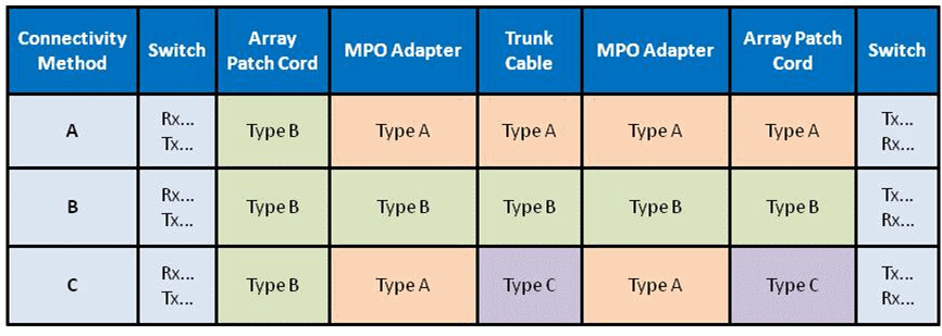
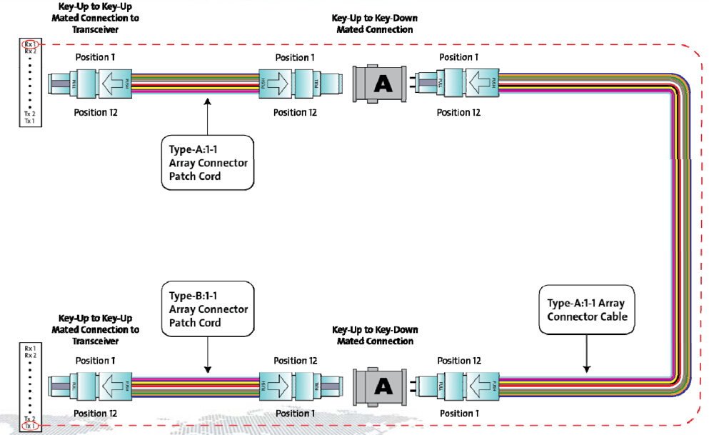
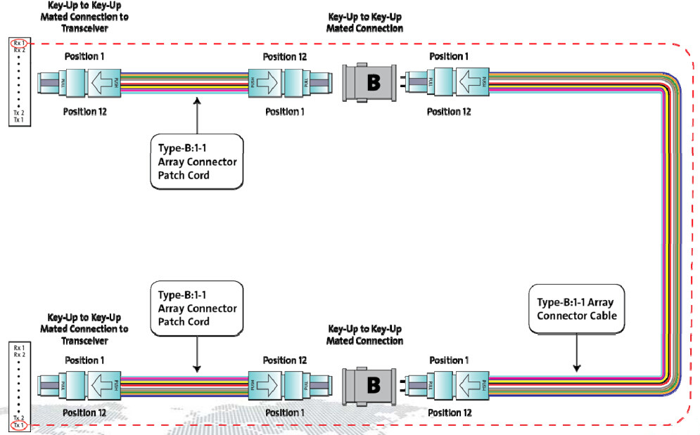
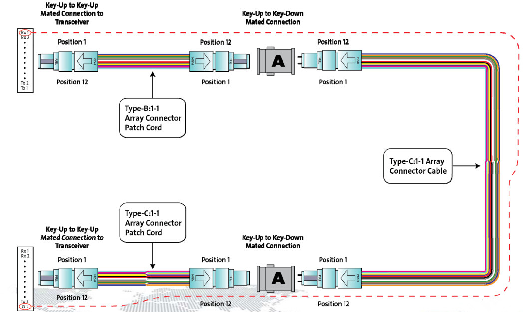
As we know, the purpose of array connectivity methods is to create an optical path from the transmit port of one device to the receive port of another device. Different polarity methods to accomplish this goal may be implemented. However, these different methods may not be inter-operable. Any connectivity method requires a specific combination of components to maintain polarity. Figure 1 illustrates the corresponding connectivity methods A, B and C to establish polarity for parallel signals using an MPO transceiver interface with one row of fibers.

MTP/MPO polarity methods for parallel signals 

Figure 1: Polarity Methods A, B, C for Parallel Signals

Compared with polarity methods for duplex signals, there are two differences for parallel signals. First, the MTP/MPO cassettes for duplex signals are replaced with MPO-to-MPO adapters for parallel signals. Second, the duplex fiber patch cords for duplex signals are replaced with 12-fiber patch cords for parallel signals. For the details about the polarity differences between duplex signals and parallel signals, you can read “Type A MTP Cassette and Type B MTP Cassette: When and Where to Use?” to know more information about polarity methods for duplex signals. While for polarity methods for parallel signals, keep reading this post for more information.

Connectivity Method A for Parallel Signals
 
When connecting arrays for parallel signals, the Type A backbone is connected on each end to a patch panel. On one end of the optical link, a Type A array patch cord is used to connect patch panel ports to their respective parallel transceiver ports. On the other end, a Type B array patch cord is used to connect panel ports to their respective parallel transceiver ports. In each optical path, there shall be only one Type B array patch cord.

connectivity method A for parallel signals 

Figure 2: Connectivity Method A for Parallel Signals

Connectivity Method B for Parallel Signals
 
When connecting parallel signals, the Type B backbone is connected on each end to a patch panel. Type B array patch cords are then used to connect the patch panel ports to their respective parallel transceiver ports.

connectivity method B for parallel signals 

Figure 3: Connectivity Method B for Parallel Signals

Connectivity Method C for Parallel Signals
 
Connectivity Method C for parallel signals is similar to connectivity method A. The differences are Type C trunk cable is used instead of Type A, and a Type C cross-over patch cord is required at one end and at the other end, still Type B patch cable used.

connectivity method C for parallel signals 

Figure 4: Connectivity Method C for Parallel Signals

Connection Tips
 
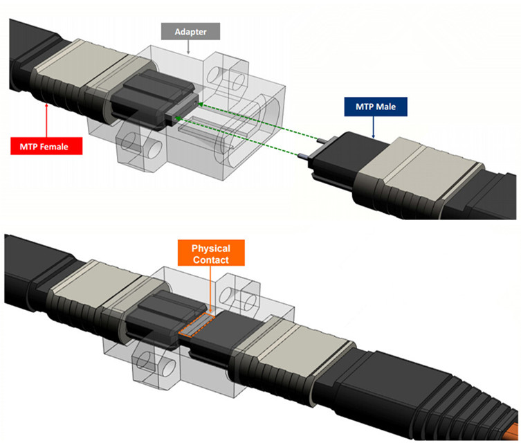
An important point to remember is that MPO plugs use alignment pins. MPO transceivers typically have pins (Male) and the patch cords from transceiver to patch panel are typically unpinned (Female) on both ends. Transitions (mounted behind the panel) are typically pinned (Male) on both ends. Cables from rack to rack are typically unpinned (Female) on both ends.

connection tips for parallel signals 

Figure 5: focused on the connection

The physical contact area is the critical joining point in the fiber network. If there is not a clean physical connection, the light path is disrupted and the connection is compromised.

Conclusion
 
No matter for duplex signals or for parallel signals, there are three types of polarity methods A, B and C. Parallel optical fiber links integrate multiple transmitters in one transmitter module, multiple fibers in fiber array connectors, and multiple receivers in one receiver module. When mating connectors that use alignment pins, it is critical that one plug is pinned and the other plug is unpinned. Typically, the pinned connector is located inside the panel. In other words, the fixed connector is pinned and the connector that is frequently removed and handled in unpinned. Hope the information in this article can help you better understand the MTP/MPO polarity methods for parallel signals.


2017年4月25日星期二

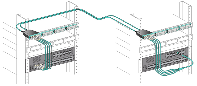
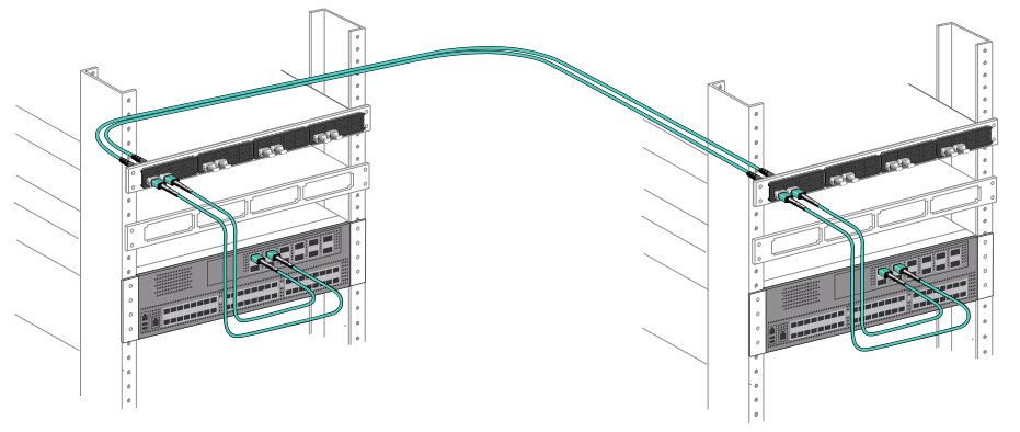
No Conversion vs. Conversion Module vs. Conversion Harness: Which to Use for 40G Parallel Solution?

When talking about 40G cabling, MPO cable is the most common choice for data center managers to use. Today, I’d like to talk about three types of MTP cabling options for 40G parallel connectivity. The first type is to deploy MPO 12 cable and ignore the unused four fibers. And the other two types are using conversion module or conversion harness to convert two 12-fiber links into three 8-fiber links. So the three cabling options—no conversion vs. conversion module vs. conversion harness: which to use for 40G parallel solution?

Solution 1: No Conversion
 
For no conversion scenario, 12-fiber based MTP trunk cables are deployed in the whole 40G connectivity. But in this situation, 33% fiber is not used. And there will be additional cost associated with the purchase of additional fiber. Moreover, the whole system includes unused fibers.

no conversion solution, the whole link uses base-12 mtp cables 

Figure 1: no conversion used, the whole link uses base-12 MTP/MPO cable

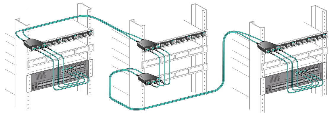
Solution 2: Conversion Module
 
With using conversion module, it can convert the unused fibers into usable fiber links. For every two 12-fiber MTP connectors in the backbone cable, you can create three 8-fiber links. Although there will be additional cost for the additional MTP connectivity, it can be offset by the cost savings from 100% fiber utilization in the structured cabling. When reusing existing deployed MTP cabling, great value will be gained if using conversion module to use all previously deployed fiber, and you eliminate the cost of having to deploy additional cabling.

conversion module solution, use conversion module to convert 12-fiber link into 8-fiber link 

Figure 2: use conversion module to convert two 12-fiber links into three 8-fiber links

Solution 3: Conversion Harness
 
This scenario uses standard MTP patch panels and 2x3 MTP conversion harness. It does not add any connectivity to the link and full fiber utilization is achieved. Although it seems attractive, it involves considerable cabling challenges. For instance, if you only need two 40G connections to the equipment, what do you do with the third 8-fiber MTP connection? Or what if the 40G ports are in different chassis blades or completely different chassis switches? The result will be long assemblies, which will be difficult to manage in an organized way. For this reason, this kind of solution is expected to be the least desirable and so the least deployed method.

Conversion harness solution, use conversion harness to convert 12-fiber link into 8-fiber link 

Figure 3: use conversion harness to convert two 12-fiber links into three 8-fiber links

No Conversion vs. Conversion Module vs. Conversion Harness
 
For the three types of connectivity solutions, the “No Conversion” solution, using traditional 12-fiber MTP connectivity and ignoring unused fibers, has the advantage of simplicity and lowest link attenuation. And as it does not use 33% of the installed fiber, it then requires more cable raceway congestion.

The “Conversion Module” solution, converting two 12-fiber links into three 8-fiber links through a conversion patch panel, uses all backbone fibers and creates a clean, manageable patch panel with off-the-shelf components. But it would lead to additional connectivity costs and attenuation associated with the conversion device.

The “Conversion Harness” solution, converting two 12-fiber links into three 8-fiber links through a conversion harness and standard MTP patch panel, uses all backbone fibers with additional connectivity. But it would create cabling challenges with dangling connectors and non-optimized-length patch cords that require customization.

Generally, the implementation of the conversion module solution is recommended, especially if you are using previously installed MTP trunks. Conversion module solution allows 100% fiber utilization while maintaining any port to any port patching. And if you are installing new cabling, then you can consider the no conversion solution, assuming that the cable raceway is not a concern. The conversion harness solution is typically deployed only in specific applications, such as at the ToR switch, where 40G ports are in a close cluster and patching between blades in a chassis switch is not required.

Conclusion
 
From what have described above, have you had a better understanding of these three types of 40G cabling solution? Each type has their own advantages and disadvantages. For those three solution choices—no conversion vs. conversion module vs. conversion harness: which is your choice for 40G parallel solution?

2017年4月17日星期一

MTP Base-8 and Base-12: Correct Using Principles

In my previous post “MTP Links: Base-8 vs. Base-12 vs. Base-24”, I have done a comparison among Base-8 MTP, Base-12 MTP and Base-24 MTP. And from the post, we can conclude that Base-8 MTP link is the most future-proof option for the quickly-changing network requirements. But someone may ask “I have deployed Base-12 or Base-24 MTP link. Can I still deploy Base-8 MTP connectivity in the network? Or will Base-8 connectivity fit all applications?”. This post will answer these questions. Keep reading, you’ll get more.

Can Base-8 and Base-12 Be Used Together: Yes Or No?
 
The answer of this question depends. If directly mix the components and plug a Base-8 MTP cable into a 12-fiber module, then the answer is “No”. Base-8 components and Base-12 components are not designed to be plugged directly into each other. Generally, Base-12 MTP trunk cables have unpinned (female) MTP connectors on both ends, and require the use of pinned (male) breakout modules. But the Base-8 MTP trunk cables are manufactured with pinned connectors on both ends. So plugging a Base-8 trunk cable into a Base-12 breakout module will definitely not work. However, Base-8 and Base-12 MTP connectivity can be used in the same data center, but they should be maintained independently. As they are not interchangeable, some care is needed when managing the data center physical layer infrastructure, to ensure Base-8 and Base-12 components are not mixed within the same link.

MTP link working principle: yes or no 

Will One Type Fit All?
 
As known to all, 12-fiber MPO connectors are common in data centers, but they pose a problem when installed in a parallel path system—four unused fibers remain per connection. Typically, Base-8 can be a more cost-effective option for end-to-end MPO to MPO channels and architectures. Deploying Base-8 connectivity in duplex architectures for 10GBASE-SR and 25GBASE-SR will save 4% to 5% for data center managers, but if you’re running groups of 6-ports, Base-8 may result in a significant cost increase. Generally speaking, not one size fits all. Base-8 connectivity isn’t a universal solution. In fact, in some cases, Base-12 may still be more cost-effective. So it’s best to have both Base-8 and Base-12 connectivity in the same data center through careful management and labeling practices.

Summary
 
From what have described above, we can get these points. Although Base-8 and Base-12 MTP connectivity are not interchangeable, but they can be used in the same data center as long as the links are maintained separately. Base-8 and Base-12 MTP fiber links cannot be mixed and matched. Moreover, there is no one connectivity method fitting for all network applications. Base-8 connectivity method and Base-12 connectivity method can be used in different applications that can make the most of each type. For the most commonly 10G to 40G migration, Base-8 connectivity would be a strong consideration over Base-12.

 
Other post you may be interested: MTP-8 Solution: Future-Proof Connectivity in Data Center

2017年4月14日星期五

MTP Link Performance: Higher Fiber Count vs. Lower Fiber Count

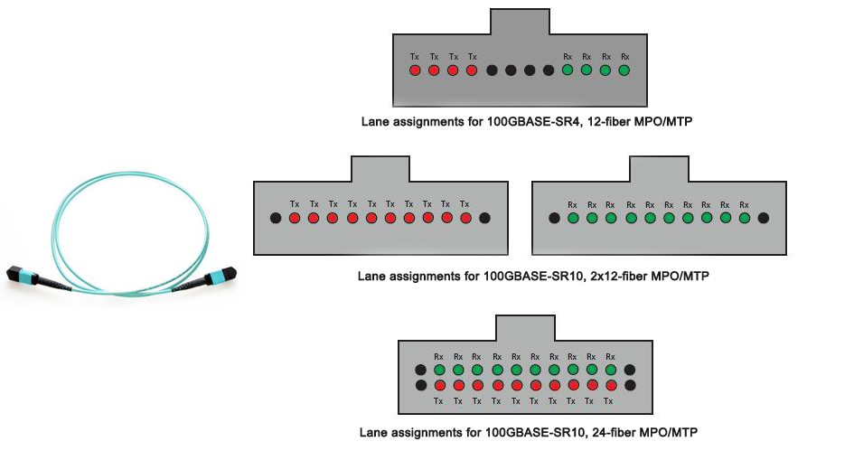
With the pre-terminated plug & play benefits and ease of scalability from 10-40-100G, MPO/MTP connectors are rapidly becoming the norm of switch-switch connections. In the previous post “Introduction to MPO Connector”, I have talked about two types of MPO connectors—12 fiber MPO connector and 24 fiber MPO connector. And both the two MPO/MTP cable types can be used for 100G data transmission. So someone may ask “for MTP link performance, is there any difference between higher fiber count and lower fiber count, or, which produces better performance, higher fiber count or lower fiber count?”. This post simply tells the answer.

12-fiber MPO vs. 24-fiber MPO 

MTP Link: Higher Fiber Count ≠ Higher Insertion Loss
 
Generally, lower overall optical loss allows more margin for the network to operate, or in the case for some users, offers the option of more connections for patching locations. Then some network designers claim that higher fiber count will lead to higher insertion loss. Actually, this point of view is wrong. For both 12-fiber and 24-fiber MPO connector performance, the industry standard product rating is 0.5 dB maximum. When using proper polishing techniques, 24-fiber MPO/MTP terminations can meet the same performance levels as 12-fiber MTP assemblies. Furthermore, using low-loss ferrules, both 12 fiber and 24 fiber MPO connectors can be rated at 0.35 dB maximum.
 
MTP Link: Higher Fiber Count = Higher Performance
 
As you know, both MPO 24 fiber cable and MPO 12 cable can be used in 100G applications. MPO 12 cable can be used in 4x25G solutions, remaining 4 fibers unused. By using MPO 24 fiber cable, it can be converted into three 8-fiber 100G channels that run over one cable, with all 24 fibers used to support traffic. Let’s show an example to further prove which is better. If you need to support twelve 100G channels with the 4x25G standard, using 12 fiber MPO cable, you need to install 12 connectors, or 144 fibers total, with 33% of the fiber wasted. Using MPO 24 fiber cable supporting the same 12 channels, only 4 cables would be required, using 96 fibers total, at 100% fiber utilization.

Summary
 
From what have described above, we can summarize that MPO 24 fiber cable does not translate into higher insertion loss and can work as well as MPO 12 cable. Moreover, the 24 fiber MPO cable, while allowing the use of the ratified 100GBASE-SR10 20-fiber technology, can at the same time maximize the installed infrastructure investment in the event of 4x25G ratification and ultimate implementation. Choosing MPO 12 cable simply cannot accomplish this because it drives down return on investment and subsequently increases the total cost of ownership. And this is the exact opposite of the design intent of a data center infrastructure system.

2017年4月5日星期三

MTP Links: Base-8 vs. Base-12 vs. Base-24

For data center managers, deploying a fiber system that can easily be upgraded to future high-density network demands is the first thing that should be considered, because network reconfiguration would result in lots of time and money. So it is essential to deploy a fiber network which is easier to upgrade to the higher data rates from the start. For high density MTP links, Base-8 vs. Base-12 vs. Base-24: which one can provide a easier migration path for future network data rates?

Base-8 MTP Link
 
Base-8 MTP link is based on Type B male/pinned MTP trunk in the backbone. Base-8 MTP is SR4 ready, meaning that the backbone connectivity has the same fiber count as the SR4 transceiver. Base-8 MTP links allow customers to patch directly to SR4 transceivers without having to convert connectors with different fiber counts or waste excess fibers in the backbone. As SR4 transceivers are the preferred choices for 40G, 100G data rates and beyond, the Base-8 system is arguably the most scalable and future-proof backbone choice currently available. Customers deploying 10G data rates today can still deploy the Base-8 system knowing that upgrades to 40G or 100G will be much simpler and cost effective in the future. The following picture is 1x3 MTP conversion harness cables used in 40G/100G network with 100% fiber utilization.

1x3 MTP conversion harness cable with 100% fiber utilization 

Base-12 MTP Link
 
Base-12 MTP link is based on Type A female/unpinned MTP trunk in the backbone. Base-12 MTP is partially SR4 ready, because although SR4 is an 8 fiber interface, the Base-12 MTP connector is still compatible with it. Unlike the Base-8 MTP system, Base-12 does not utilize all of the fibers in the backbone when patched directly with SR4 transceivers, however multiple Base-12 MTP connectors can be combined and then converted so that full fiber utilization can still be achieved. Take our 2x3 MTP conversion harness cables for example, these MTP conversion cables have two 12-fiber MTP connectors on one end and three 8-fiber MTP connectors on the other end, which utilize all 12 fibers in two trunks for use with three port channels.

2x3 MTP conversion harness cables with 100% fiber utilization 

Base-24 MTP Link
 
Base-24 MTP link is generally deployed for 100G parallel links running over SR10 transceivers. Normally these links are between two high data-rate switches as opposed to switch to server. Base-24 can also be used for lower data rate backbone links such as 10G and 40G but this is normally only in cases where space and install time are the key drivers.

MTP Links: Base-8 vs. Base-12 vs. Base-24
  • Initial Investment
Base-8 does require a higher up-front investment than Base-12 or Base-24 backbones due to the higher number of MTP connectors that are installed from day 1. However, research shows that the rapid increase in data rates will bring a return on investment within a few years. Furthermore, Base-8 provides the most efficient link constructions for SR4 meaning that the investment to convert Base-12 or Base-24 to SR4 will be largely if not completely avoided later.
  • Fiber Utilization
Although Base-12 backbones are still the most common choice for most data center operators today, it should be noted that there are still no standardized transceivers using all 12 fibers in a Base-12 connector. Furthermore, the most likely transceiver interface SR4 in the future uses only 8 fibers. With this in mind, customers need to make the important decision whether to deploy Base-12 today and risk wasting 33% of backbone fibers tomorrow, or go straight for Base-8 knowing that it will be the best investment for the future.
  • No. of Cables
Compared to Base-8 or Base-12, Base-24 reduces the number of cables required in the link, and sometimes this can be a compelling driver towards using this particular interface in the backbone. However, it should be noted that deploying Base-24 as a backbone choice will require MTP transition modules or MTP conversion harness to make it suitable for 10G and 40G data rates.

Summary
 
From what have described above, we can see that Base-8 MTP link, Base-12 MTP link and Base-24 MTP link have their own cons and prons. Base-8 MTP trunks allow users to build 10G links today but can easily be upgraded to 40G links tomorrow using 8 fiber MTP connectivity. Base-12 and Base-24 MTP trunks allow users to build 10G links today, which can easily be upgraded to 40G/100G links tomorrow using MTP conversion modules, MTP conversion harness or jumpers, but would result in 33% fiber wastage. MTP Links: Base-8 vs. Base-12 vs. Base-24: which is your choice?

 
12-Fiber or 24-Fiber MTP/MPO Cabling: Which Is Better for 40G/100G Network?