2017年2月7日星期二

Four Types of 100G QSFP28 Transceivers Overview

For 100G optical transceivers, there are a number of form factors including CFP/CFP2/CFP4, CXP and QSFP28. Among these different 100G form factors, it appears that the market has chosen QSFP28 as the primary form factor for 100G links. Hence, this post will focus on several types of 100G QSFP28 transceivers—100GBASE-SR4 QSFP28 transceiver, 100GBASE-PSM4 QSFP28 transceiver, 100GBASE-LR4 QSFP28 transceiver, and 100GBASE-CWDM4 QSFP28 transceiver.

100GBASE-SR4 QSFP28 Transceiver
 
The 100GBASE-SR4 QSFP28 transceiver is a parallel 100G optical transceiver. It provides increased port density and total system cost savings. The QSFP28 full-duplex optical transceiver offers 4 independent transmit and receive channels, each capable of 25 Gbps operation for an aggregate data rate of 100 Gbps on 100 meters over OM4 MMF. Generally, 100GBASE-SR4 QSFP28 transceiver converts parallel electrical input signals into parallel optical signals by a driven VCSEL array. The transmitter module accepts electrical input signals compatible with CML (common mode logic) levels. All input data signals are differential and internally terminated. The receiver module converts parallel optical input signals via a photo detector array into parallel electrical output signals. The receiver module outputs electrical signals are also voltage compatible with CML levels. All data signals are differential and support a data rates up to 25 Gbps per channel.
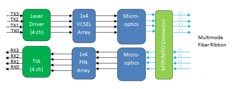
100GBASE-SR4 QSFP28 Transceiver diagram
 
100GBASE-PSM4 QSFP28 Transceiver
 
The 100GBASE-PSM4 QSFP28 transceiver is a parallel 100G single-mode optical transceiver with an MTP/MPO fiber ribbon connector. It uses 8 fibers (4 transmit and 4 receive), each transmitting at 25 Gbps, resulting in an aggregate data rate of 100 Gbps on 500 meters over SMF. The working principle of 100GBASE-PSM4 QSFP28 transceiver is nearly the same with the 100GBASE-SR4 QSFP28 transceiver. The only difference is that PSM4 works over SMF, while SR4 works over OM4 MMF.
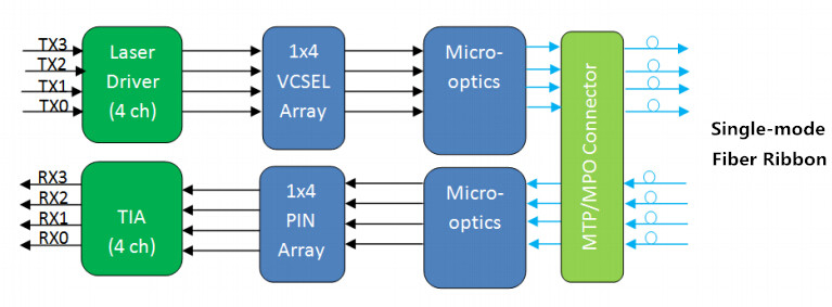
100GBASE-PSM4 QSFP28 Transceiver diagram
 
100GBASE-LR4 QSFP28 Transceiver
 
The 100GBASE-LR4 QSFP28 transceiver converts 4 input channels of 25 Gbps electrical data to 4 channels of LAN WDM optical signals and then multiplexes them into a single channel for 100G optical transmission. On the receiver side, the module demultiplexes a 100G optical input into 4 channels of LAN WDM optical signals and then converts them to 4 output channels of electrical data. The central wavelengths of the 4 LAN WDM channels are 1295.56, 1300.05, 1304.58 and 1309.14 nm as members of the LAN WDM wavelength grid defined in IEEE 802.3ba. The 100GBASE-LR4 QSFP28 transceiver provides superior performance for 100G applications up to 10 km over SMF and compliant to optical interface with IEEE802.3ba 100GBASE-LR4 requirements.
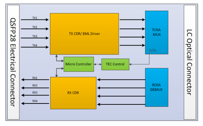
100GBASE-LR4 QSFP28 Transceiver diagram
 
100GBASE-CWDM4 QSFP28 Transceiver
 
The 100GBASE-CWDM4 QSFP28 transceiver is a full duplex optical transceiver that provides a high-speed link at aggregated data rate of 100 Gbps over 2 km on SMF. The transmitter path converts four lanes of serial electrical data to optical signal. The optical signals from the four lasers are optically multiplexed and coupled to single-mode fiber through an industry standard LC optical connector. The optical signals are engineered to meet the CWDM4 MSA specifications. On the receive side, the four incoming wavelengths are separated by an optical demultiplexer into four separated channels.
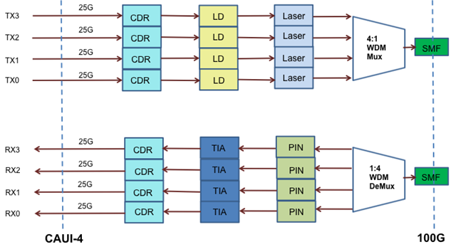
100GBASE-CWDM4 QSFP28 Transceiver diagram
 
Summary
 
This article has introduced the basic information about 100GBASE-SR4 QSFP28 transceiver, 100GBASE-PSM4 QSFP28 transceiver, 100GBASE-LR4 QSFP28 transceiver, and 100GBASE-CWDM4 QSFP28 transceiver. The following table summarizes the differences of these four types of 100G QSFP28 transceivers. You should first make clear each type and then choose the one that best suits your network demands. In addition to the generic ones mentioned in this post, we also have other 100G QSFP28 transceivers compatible with major brands such as Cisco, etc. For the detailed information, you can visit www.fs.com.

Transceiver TypeInterfaceTransmission Distance
100GBASE-SR4 QSFP28 TransceiverMTP/MPO-12100m over 8 MMFs
100GBASE-PSM4 QSFP28 TransceiverMTP/MPO-12500m over 8 SMFs
100GBASE-LR4 QSFP28 TransceiverLC duplex10km over 2 SMFs
100GBASE-CWDM4 QSFP28 TransceiverLC duplex2km over 2 SMFs

Related Article: QSFP28 – A Better Way to 100G

Originally published: www.fiberopticshare.com/100g-qsfp28-transceivers-overview.html
2017年2月4日星期六

How to Set up Wireless Network?

A wireless network is completely wireless, which means that any device with a WiFi networking card installed will be able to access the Internet provided you have the right password. Wireless networks are surely convenient for the daily life. This post tells about the things you should consider before building the wireless network, and then list the procedures of setting up wireless network.

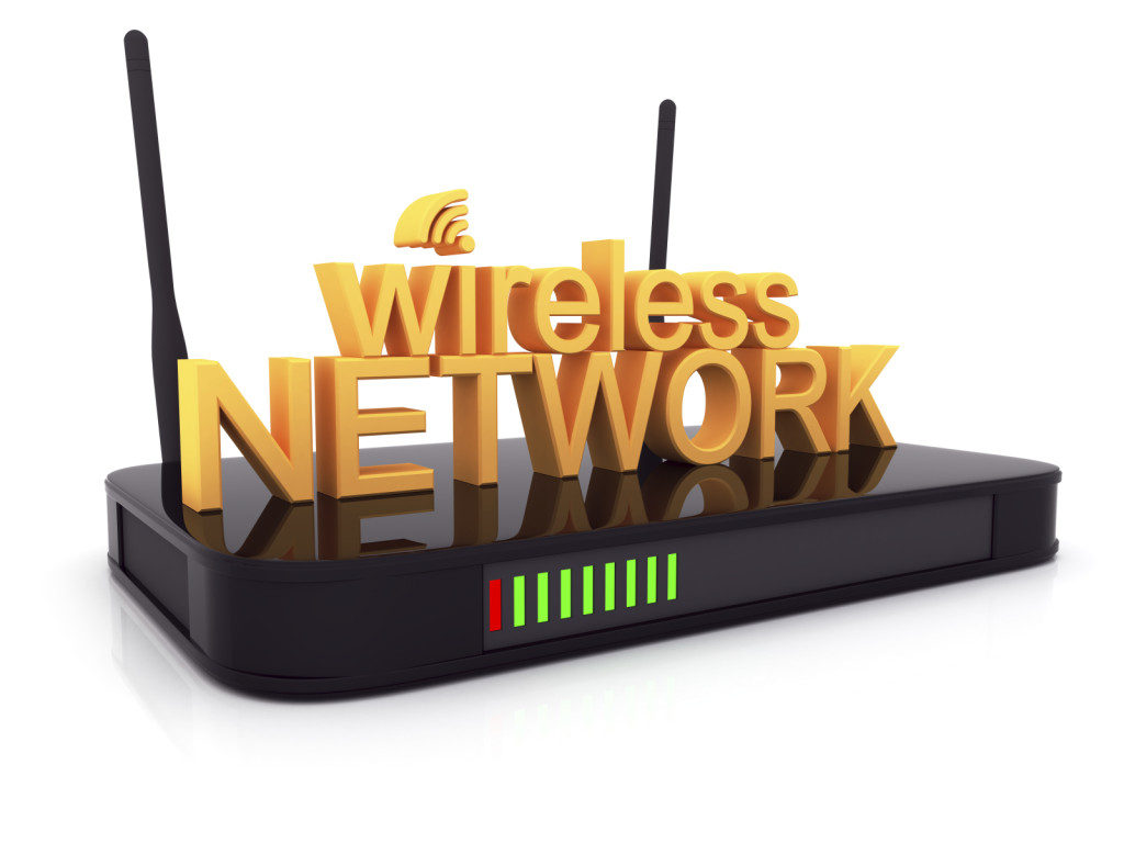
wireless network 

Things to Consider Before Taking Action
 
Before building your own wireless network, you should make clear the following points.

First, what you are going to use the wireless network for. Make sure you determine this ahead of time so that you can decide how much speed and coverage you will need. Obviously, the more you want to do with your wireless network, the faster it will need to be. Remember that the more devices you connect to your network, the more speed is divided among them. Too many devices will significantly lower network performance.

Second, confirm how much coverage you will need for your wireless network. If the house is too big, you may need to install more than one access point, which will require configuration. Keep in mind that the construction of the house can affect the coverage of your wireless network. Some walls are made of extra thick concrete that will reduce coverage in your network.

Last, determine where you will place your wireless access point. To get maximum coverage, it’s best to place it in a location that is elevated and away from sources of interference. You can also put the access point near the center of the area where you’ll be operating the majority of your wireless equipment. Keep in mind that your neighbors’ wireless networks may interfere with yours, and vice versa, if theirs is installed with the default channel settings.

wireless access point 

How to Set up Wireless Network?
 
All you need for a wireless network is a wireless router, a computer or laptop with wireless capabilities, a modem and two Ethernet cables. Follow the instructions below to setup your wireless network.

1. Find the best location for your wireless router.

2. Turn off the modem. Power off the cable or DSL modem from your ISP before connecting your equipment.

3. Connect the router to the modem. Plug an Ethernet cable into the router’s WAN port and then the other end to the modem.

4. Connect your laptop or computer to the router. Plug one end of another Ethernet cable into the router’s LAN port and the other end into your laptop’s Ethernet port.

5. Power up the modem, router, and computer in turn.

6. Go to the management web page for your router. Open a browser and type in the IP address of the router's administration page.

7. Change the default administrator user name and password for your router. This setting is usually found in a tab or section called administration. Remember to use a strong password that you won't forget.

8. Add WPA2 security. This step is essential. You can find this setting in the wireless security section, where you'll select which type of encryption to use and then enter a passphrase of at least 8 characters—the more characters and the more complex the password, the better.

9. Change the wireless network name (SSID). To make it easy for you to identify your network, choose a descriptive name for your SSID (Service Set Identifier) in the wireless network information section.

10. Change the wireless channel. If you’re in an area with a lot of other wireless networks, you can minimize interference by changing your router's wireless channel to one less used by other networks. You can use a WiFi analyzer app for your smartphone to find the least crowded channel or just use trial and error (try channels 1, 6, or 11, since they don't overlap).

11. Set up the wireless adapter on the computer. After saving the configuration settings on the router above, you can unplug the cable connecting your computer to the router. Then plug your USB or PC card wireless adapter into your laptop, if it doesn't already have a wireless adapter installed or built-in. Your computer may automatically install the drivers or you may have to use the setup CD that came with the adapter to install it.

12. Finally, connect to your new wireless network. On your computer and other wireless-enabled devices, find the new network you set up and connect to it.

Summary
 
After reading this post, have you understood how to set up wireless network? To maximize the WiFi performance, you should confirm the coverage and find the best place for the wireless access point. And then set up the wireless network step by step. We provide a series of solutions for wireless access service. For more details, please visit www.fs.com.


PON Fault Scenarios and Troubleshooting Basics

A PON network consists of an OLT connected via a PON splitter to multiple ONTs (one for each subscriber, up to 64 subscribers). Sometimes, a second splitter can be connected in cascade to the first splitter to dispatch services to buildings or residential areas, which has been introduced more clearly in the previous post “Understanding the Split Ratios and Splitting Level of Optical Splitters”. This post will tell about troubleshooting of a point-to-multipoint FTTH network, also defined as a PON network.

simple PON architecture with one splitter
cascaded PON architecture with more than one splitter

PON Fault Scenarios
Scenario 1: Simple PON (only one customer is affected)

There are three potential faults when only one subscriber cannot receive service—fault in the distribution fiber between the customer and the closest splitter, or fault in the ONT equipment, or fault in the customer’s home wiring.

PON fault scenario
PON fault scenario

Scenario 2: Cascaded PON (all affected customers are connected to the same splitter)

When all customers connected to the same splitter cannot receive service, but others connected to the same OLT can, the cause may be one of the two—fault at the last splitter, or fault in the fiber link between the cascaded splitters.

PON fault scenario

Scenario 3: All customers are affected (at the OLT level)

Whether or not the PON is cascaded, all customers dependent on the same OLT may be affected. If all customers are affected, the cause may be from of the three—fault in the splitter closest to the OLT, or fault in the feeder fiber cable of the network, or fault in the OLT equipment.

PON fault scenario

PON Troubleshooting Basics
Troubleshooting a PON first involves locating and identifying the source of an optical problem. The following picture offers a complete view of all of the possible fault locations depending on how many customers are affected, and the best location to shoot an OTDR.

PON troubleshooting

Generally, most PON problems can be located using PON power meter and PON-optimized OTDR. The power meter is connected as a pass-through device, allowing both downstream and upstream traffic to travel unimpeded. It measures the power at each wavelength simultaneously and can be used for troubleshooting at any point in the network. A monitoring OTDR provides a graphical trace that enables to locate and characterize every element in a link, including connectors, splices, splitters, couplers and faults. OTDRs designed specifically for in-service PON troubleshooting exist. These OTDRs feature a dedicated port for testing at 1625 or 1650 nm and incorporate a filter that rejects all unwanted signals (1310, 1490 and 1550 nm) that could contaminate the OTDR measurement. Only the OTDR signal at 1625 or 1650 nm is allowed to pass through the filter, generating a precise OTDR measurement. In-service OTDR troubleshooting of optical fiber should be done in a way that does not interfere with the normal operation and expected performance of the information channels. Testing with the 1625 or 1650nm wavelength does just that. A PON-optimized OTDR does not interfere with the CO’s transmitter lasers because the 1650nm wavelength complies with the ITU-T L.41 Recommendation. The addition of a broadband filter, acting as a 1625 or 1650nm testing port at the CO’s WDM coupler, may be beneficial. And the quality of service provided to other subscribers serviced by the same 1xN splitter is not affected. Consequently, the technician can connect the OTDR’s 1625 or 1650nm port to the ONT and send the signal toward the CO. If a 1625 or 1650nm testing port is added to the CO, it is also possible to perform tests from the CO down to the ONT, but a 1625 or 1650nm filter may be needed at each ONT.

Summary
PON troubleshooting should first find the fault locations of the network. This post lists three types of potential fault scenarios for your reference. After knowing where the fault is, then you should use the correct tools to test and verify. PON power meter and OTDR can help significantly during the testing process. If you are confused about PON troubleshooting, hope the information in this post will be helpful.

2017年1月22日星期日

How to Install and Connect CWDM System?

CWDM system is able to provide optical networking support for high-speed data communication for metropolitan area networks (MANs). And in some previous articles, I have talked a lot about CWDM, such as the components used in CWDM system. In this article, I’d like to have an introduction to CWDM system installation and connection.

Procedures for CWDM System Installation
The CWDM system includes the system shelf, CWDM OADM, CWDM Mux/Demux and CWDM transceivers. You must first install the system shelf, then the CWDM OADM and CWDM Mux/Demux, followed by the CWDM transceivers you want to install.

Install the System Shelf
Follow the steps below to mount the system shelf on an equipment rack:

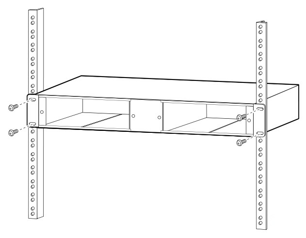
1. Align the mounting holes in the L brackets with the mounting holes in the equipment rack.

2.Secure the system shelf using four screws through the elongated holes in the L bracket and into the threaded holes in the mounting post.

secure system shelf 

3.Use a tape measure and level to ensure that the system shelf is mounted straight and level.
 
Install the CWDM OADM and CWDM Mux/Demux (Plug-in Module)
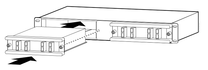
1.Loosen the captive screws on the blank plug-in module faceplate and remove the faceplate.

2.Align the plug-in module with the slot on the system shelf.

install cwdm mux 

3.Gently push the plug-in module into the system shelf slot. Ensure that you line up the captive screws on the plug-in module with the screw holes on the shelf.

4.Tighten the captive screws.

Remove the CWDM OADM and CWDM Mux/Demux (Plug-in Module)
1.Loosen the captive screws on each side of the plug-in module using a screwdriver.

2.Gently pull on both captive screws to release the plug-in module from the shelf.

3.Pull the plug-in module out of the shelf.

4.Replace the blank plug-in module faceplate if you do not intend to install another plug-in module.

Install a CWDM Transceiver
1.Remove the CWDM transceiver from its protective packaging.

2.Verify that the CWDM transceiver is the correct model for your network configuration.

3.Remove the dust covers from the CWDM transceiver’s optical bores.

4.Grasp the sides of the CWDM transceiver with your thumb and forefinger.

5.Insert the CWDM transceiver into the correct slot on your switching module. You should hear a click when the transceiver has been properly seated into the slot.

Remove a CWDM Transceiver
1.Disconnect the fiber optic patch cable.

2.Release the CWDM transceiver from the slot by simultaneously squeezing the plastic tabs.

3.Pull the CWDM transceiver out of the slot.

4.Install the plug in the CWDM transceiver optical bores and place the CWDM transceiver in protective packaging.

Procedures for CWDM System Connection
This part tells how to connect the CWDM system to the switch.

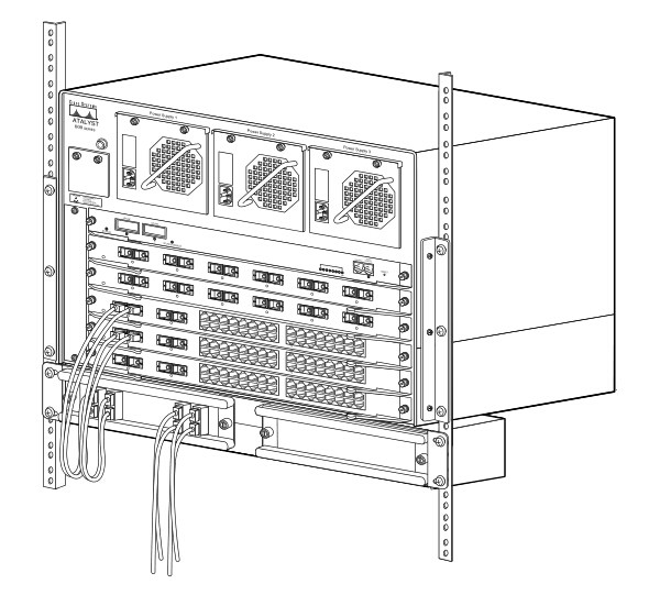
Connect Cables to a CWDM OADM
1. Insert the CWDM transceivers into the appropriate connectors on your switch if you have not already done so.

2. Insert the CWDM transceivers (color code/wavelength specific) into their respective switching module ports.

3. Clean all fiber optic connectors on the cabling before inserting them into the CWDM Mux/Demux connectors.

4. Connect the single-mode fiber optic patch cable from the CWDM transceiver (TX/RX) to the OADM module equipment connectors (TX/RX).

5. If you are using both channels of the CWDM OADM, then repeat step 4 for the second channel.

6. Connect the west backbone single-mode fiber patch cable to the OADM network west connector and connect the east backbone single-mode fiber patch cable to the OADM network east connector.

install CWDM OADM 

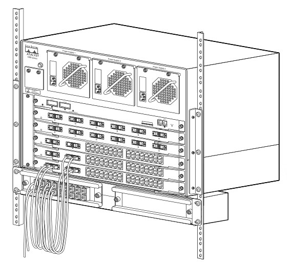
Connect Cables to a CWDM Mux/Demux (8-Channel)
1.Insert the CWDM transceivers (color code/wavelength specific) into their respective switches.

2.Clean all fiber optic connectors on the cabling before inserting into them into the 8-channel CWDM Mux/Demux connectors.

3.Connect the single pair fiber optic cables from the CWDM transceivers (TX/RX; up to eight channels) to the OADM module equipment connectors (TX/RX; up to eight wavelengths).

4.Connect the backbone single pair fiber optic patch cables to the OADM network connector.

5.Connect the fiber optic patch cables from the CWDM transceivers (TX/RX) to the 8-channel Mux/Demux (TX/RX) connectors.

install CWDM MUX/DEMUX 

Summary
This article provides installation instructions for the CWDM system, which includes the system shelf installation, CWDM OADM and CWDM Mux/Demux installation and removal, CWDM transceivers installation and removal as well as connecting the CWDM OADM and CWDM Mux/Demux to the switch. The optical components used in this process are as follows.

Originally published: www.fiberopticshare.com/install-connect-cwdm-system.html

2017年1月13日星期五

Introduction to the Components Used in CWDM System

CWDM system is a passive optical solution for increasing the flexibility and capacity of existing fiber lines in high-speed networks. It increases fiber capacity by placing widely spaced, separate wavelengths (between 1310 nm and 1610 nm) from multiple ports onto a single-mode fiber pair on the network. The CWDM system components are passive and require no power supplies. This article will introduce the components used in CWDM system.

CWDM System Components
 
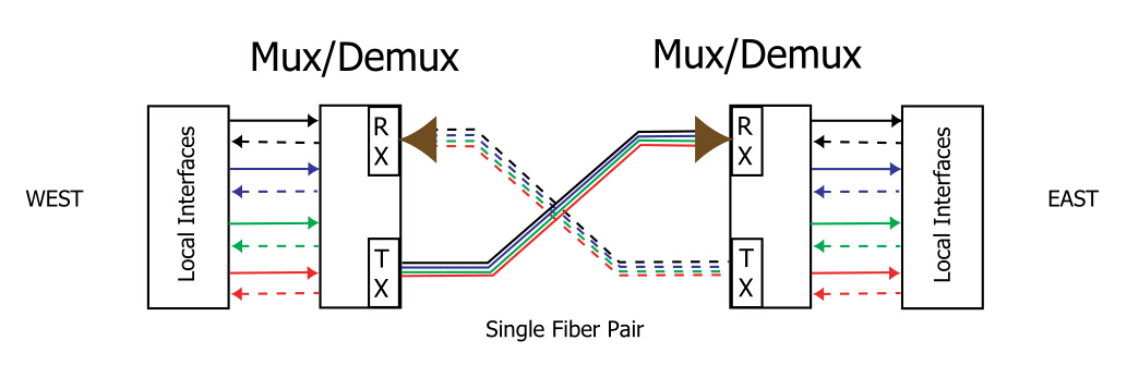
Generally, there are three basic components in a CWDM system, which are the multiplexer/demultiplexer (Mux/Demux), the drop/pass module and drop/insert module. CWDM applications are described in terms of an east-west connection. Different colors represent individual channels. Westbound traffic is represented by dashed lines, while eastbound traffic is shown with solid lines.

mux/demux 

Mux/Demux
 
The Mux/Demux based on film filter is the most mature component used in CWDM system. It combines different channels onto a single outbound (TX) fiber. Simultaneously, the Mux/Demux receives the same channels from a single inbound (RX) fiber, separates them into individual wavelengths, and delivers each to the appropriate local interface. This process expand the capacity of the existing network fiber cable. The following is an example of four channel Mux/Demux.

Mux/Demux 

The four-channel Mux/Demux can be configured to support additional channels through the expansion port. By cascading the modules in series, you can increase the total number of available network channels. The channels connecting to the expansion port must differ from those on the Mux/Demux to which they are being cascaded.

Drop/Pass Module
 
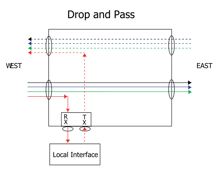
The drop/pass module removes one wavelength-specific channel from the east-bound fiber and allows the remaining channels to pass straight through to other nodes along the network. When the drop/pass module drops the channel from the network, it sends the data to a local interface. The local interface sends the same channel back to the drop/pass module for transmission in the westbound direction, thus completing the point-to-point connection between the local interface and another device located in the west. That other device may be a Mux/Demux, drop/pass, or drop/insert module.

drop and pass 

Drop/Insert Module
 
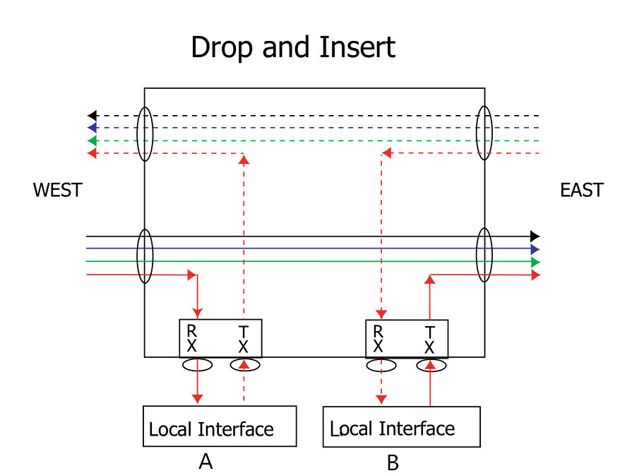
The drop/insert module provides two local interface ports. One port removes a wavelength-specific channel from the network fiber in one direction, and the other port adds that same channel back onto the fiber in the opposite direction. Because the drop/insert module supports two separate pathways going in opposite directions, network viability in a ring topology is ensured even if there is a break in the network.

On the west side, the drop/insert module removes a wavelength-specific channel from the eastbound fiber and sends it to Local Interface A. To complete the westbound connection, the drop/insert module receives the same channel from Local Interface A and inserts it onto the westbound fiber. The same happens on the east side, except in the opposite direction. The drop/insert module removes the channel from the westbound fiber and sends it to Local Interface B. To complete the eastbound connection, the drop/insert module receives the same channel from Local Interface B and inserts it onto the east-bound fiber. The drop and insert completes the point-to-point connections between the two local interfaces and two other devices located in the east and west. The other device may be a Mux/Demux, drop/pass, or drop/insert module.

drop and insert 

Summary
 
CWDM is a simple and affordable method to maximize existing fiber by decreasing the channel spacing between wavelengths. Since CWDM is a passive technology, it allows for any protocol to be transported over the link, as long as it is at a specific wavelength. Because the multiplexers simply refract light at any network speed, regardless of the protocol being deployed, CWDM can help to future proof the networking infrastructure. In all, CWDM is a low-cost and effortless technology to implement. FS.COM provides a whole series of WDM system components including CWDM and DWDM. If you need, you can visit www.fs.com for the details.


Related article: Traditional CWDM Mux/DeMux vs. FMU Series CWDM Mux/DeMux

2017年1月6日星期五

Managed Media Converter and Unmanaged Media Converter Basics

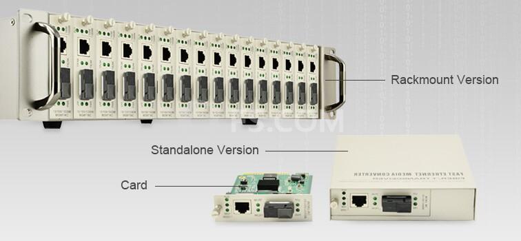
As is known to all, fiber media converter is a simple networking device which can connect two dissimilar media types such as twisted pair cable with fiber optic cable. And it can support many different data communication protocols including Ethernet, Fast Ethernet, Gigabit Ethernet, etc. According to the network to points, media converters can be divided into managed media converters and unmanaged media converters. This article will tell about these two kinds of media converters.

What Is Managed Media Converter?
 
Managed media converter supports carrier-grade network management. It is more costly than the unmanaged media converter, but it has the ability to provide additional network monitoring, fault detection and remote configuration functionality not available with an unmanaged media converter. Typically, managed media converters are equipped with remote Web / SNMP (Simple Network Management Protocol) interface, which enables network administrators to easily monitor and setup the converter, the transmission speed and duplex through web/SNMP browsers. The managed media converters are mostly suitable for those environments requiring a medium to large-scale deployment of media converters. Managed 10/100/1000 Ethernet media converter module is the smart choice for IT professionals.

managed media converter
 
What Is Unmanaged Media Converter?
 
Unmanaged media converter simply allows devices to communicate, and does not provide the same level of monitoring, fault detection and configuration as equivalent managed media converter. Connect the devices to the unmanaged media converter and they usually communicate automatically. With “plug and play” feature, unmanaged media converters are easy to install and troubleshoot. But the advantage is when a network issue is occurring, there is no way to access the media converter to see exactly what might be causing the issue. Unmanaged media converter is a great choice for newbies if you want a plug and play fiber network cable installation.

unmanaged media converter
 
When and Where to Use?
 
The managed media converters are aimed at users that require a response time of milliseconds. They are especially suitable for organizations that need to manage and troubleshoot the network remotely and securely, allowing network managers to reach optimal network performance and reliability. They can be used on any segment of a network where the traffic has to be monitored and controlled as they enable complete control of data, bandwidth and traffic. The unmanaged media converters are mostly used to connect edge devices on network spurs, or on a small stand-alone network with only a few components. They are suitable for any network that wants to simplify the installation of access points.

Summary
 
This article describes some basic information about the managed media converters and unmanaged media converters as well as their usage. The information may not be comprehensive. It’s just a reference. As a leading supplier in optical communication industry, FS.COM provides a series of managed and unmanaged media converters with various configurations. For the details, you can visit www.fs.com or contact us over sales@fs.com.

2016年12月22日星期四

How Much Do You Know About PM Patch Cables?

When talking about fiber optic patch cables, you may know LC fiber patch cables or MTP/MPO fiber cables. Besides these cables, there are some special fiber patch cables, such as mode conditioning patch cables, which has been introduced in the previous article. Today we will introduce another special fiber patch cable—polarization maintaining (PM) fiber patch cables.

Definition of PM Patch Cables
 
At the very first beginning, let’s check the basic definition about the PM patch cables. PM patch cords are based on a high precision butt-style connection technique. The PM axis orientation is maintained by using male connectors with a positioning key and a bulkhead female receptacle with a tightly toleranced keyway, ensuring good repeatability in extinction ratios and insertion losses.

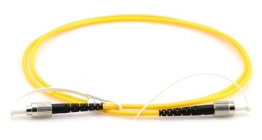
PM patch cables 

Why Need PM Patch Cables?
 
When a normal fiber is bent or twisted, stresses are induced in the fiber and the stresses will change the polarization state of light traveling through the fiber. If the fiber is subjected to any external perturbations, say changes in the fiber’s position or temperature, then the final output polarization will vary with the time. This is true for even short lengths of fiber, and is undesirable in many applications that require a constant output polarization from the fiber.

To solve this problem, PM fibers are developed. These fibers work by inducing a difference in the speed of light for two perpendicular polarizations traveling through the fiber. This birefringence creates two principal transmission axes within the fiber, known respectively as the fast and slow axes of the fiber. Provided the input light into a PM fiber is linearly polarized and orientated along one of these two axis, then the output light from the fiber will remain linearly polarized and aligned with that axis, even when subjected to external stresses. A one meter long connectorized patch cord constructed with PM fiber can typically maintain polarization to at least 30dB at 1550 nm when properly used. Naturally, how well a PM fiber maintains polarization depends on the input launch conditions into the fiber. Perhaps the most important factor is the alignment between the polarization axis of the light with the slow axis of the fiber.

Connectors of PM Patch Cables
 
Given the importance of the alignment of the PM axis across a connection, the choice of connector is especially important. The most common type of PM connector is FC connector which has a positioning key to preserve the angular orientation of the fiber. The industry standard is to align the slow axis of the fiber with the connector key. The tolerances between the key and keyway on standard FC connectors are too loose to accurately maintain angular alignment, so manufacturers have tightened the key dimension tolerances on PM connectors. The key dimensions being used are based on FC angle polished connector (APC) standards. Unfortunately, two APC standards are currently on the market, a narrow, or reduced key design, and a wide key design. The two dimensions are incompatible with one another, so it is important to know beforehand which design you are using. Besides the FC connectors, PM patch cables using other connector types are also available, such as SC connectors. In all cases, there must be a key or similar structure to act as a reference, and tight tolerances must be kept to ensure that the ferrules cannot rotate.

Conclusion
 
PM patch cables are widely used in polarization sensitive fiber optic systems for transmission of light that requires the PM state to be maintained. FS.COM provides polarization maintaining (PM) patch cables with various connector types. For the details, welcome to visit www.fs.com.