显示标签为“40G transceiver”的博文。显示所有博文

2016年3月2日星期三

Instructions for 40G QSFP+ Transceiver Installation and Removing

As is know to all, 40G QSFP+ transceiver modules are hot-swappable, parallel fiber-optical modules with four independent transmit and receive channels. These channels can terminate in another 40G QSFP+ transceiver, or the channels can be broken out to four separate 10G SFP+ transceivers. QSFP+ transceiver modules connect the electrical circuitry of the system with either a copper or an optical external network. And the transceiver, such as QSFP-40G-SR4, is used in short reach applications like switches, routers and data center equipment where it can provide higher density than SFP+ modules. This article will provide the instructions for the 40G QSFP+ transceiver installation and removing.

Required Tools
Three tools are needed to install the 40G QSFP+ transceiver modules. The first one is a wrist strap or other personal grounding device to prevent ESD (electro-static discharge) occurrences. The second one is an antistatic mat or antistatic foam to set the transceiver on. The last one is fiber-optic end-face cleaning tools and inspection equipment.

Installing 40G QSFP+ Transceivers Modules
QSFP+ transceivers have either a bail-clasp latch or a pull-tab latch. Installation procedures for both types of latches are provided.

Note: The QSFP+ transceiver module is a static-sensitive device. Always use an ESD wrist strap or similar individual grounding device when handling QSFP+ transceiver modules or coming into contact with system modules.

Follow the steps below to install a QSFP+ transceiver.

Step 1: Attach an ESD wrist strap to yourself and a properly grounded point on the chassis or the rack.

Step 2: Remove the QSFP+ transceiver module from its protective packaging.

Step 3: Check the label on the QSFP+ transceiver module body to verify that you have the correct model for your network.

Step 4: For optical QSFP+ transceivers, remove the optical bore dust plug and set it aside.

Step 5: For transceivers equipped with a bail-clasp latch, first keep the bail-clasp aligned in a vertical position. Second align the QSFP+ transceiver in front of the module’s transceiver socket opening and carefully slide the QSFP+ transceiver into the socket until the transceiver makes contact with the socket electrical connector.
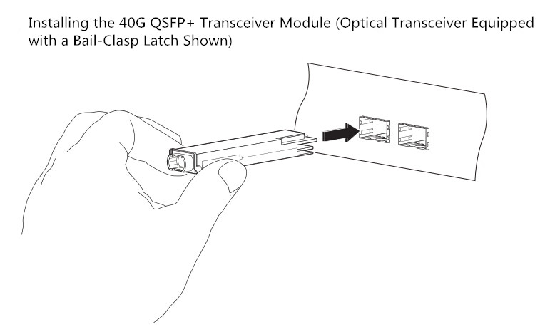
40G QSFP+
Step 6: For QSFP+ transceivers equipped with a pull-tab latch, first hold the transceiver so that the identifier label is on the top. Second align the QSFP+ transceiver in front of the module’s transceiver socket opening and carefully slide the QSFP+ transceiver into the socket until the transceiver makes contact with the socket electrical connector.

Step 7: Press firmly on the front of the QSFP+ transceiver with your thumb to fully seat the transceiver in the module’s transceiver socket.

Step 8: For optical QSFP+ modules, reinstall the dust plug into the QSFP+ transceivers optical bore until you are ready to attach the network interface cable. Do not remove the dust plug until you are ready to attach the network interface cable.

Attaching the Optical Network Cable
Note: Before removing the dust plugs and making any optical connections, please remember the following guidelines.

Firstly, keep the protective dust plugs installed in the unplugged fiber-optic cable connectors and in the transceiver optical bores until you are ready to make a connection. Secondly, inspect and clean the MPO connector or the duplex LC connector end faces before making any connections. Thirdly, grasp the MPO or the duplex LC connector only by the connector housing to plug or unplug a fiber-optic cable.

Follow the steps below to attach the optical cables.

Step 1: Remove the dust plugs from the optical network interface cable MPO connectors. Save the dust plugs for future use.

Step 2: Inspect and clean the MPO or duplex LC connector’s fiber-optic end faces.

Step 3: Remove the dust plugs from the QSFP+ transceiver module optical bores.

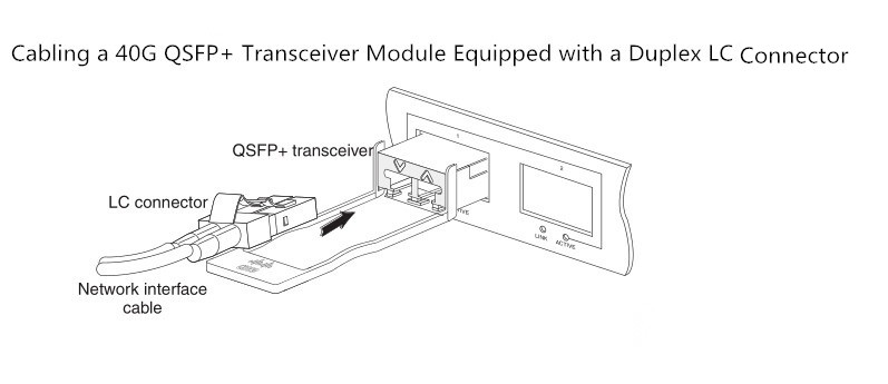
Step 4: Immediately attach the network interface cable MPO connector or duplex LC connector to the QSFP+ transceiver module.
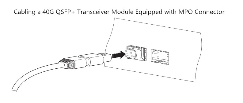
QSFP+ transceiver
LC connector
Step 5: Verify that the optical network cable is fully seated by pulling gently on the cable’s MPO or duplex LC connector boot. If the network cable disconnects, reinstall it and make sure that the cable connector is fully seated and that the connector latch engages.

Removing 40G QSFP+ Transceiver Modules
Follow the steps below to remove a QSFP+ transceiver.

Step 1: For optical QSFP+ transceivers, disconnect the network interface cable from the QSFP+ transceiver connector.

Step 2: For QSFP+ transceivers equipped with a bail-clasp latch, first pivot the bail-clasp down to the horizontal position. Second immediately install the dust plug into the transceivers optical bore. Third grasp the sides of the QSFP+ transceiver and slide it out of the module socket.
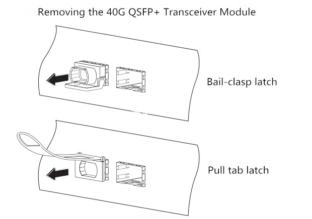
40G transceiver
Step 3: For QSFP+ transceivers equipped with a pull tab latch, first install the dust plug into the transceiver’s optical bore immediately. Second grasp the tab and gently pull to release the transceiver from the socket. Third slide the transceiver out of the socket.

Step 4: Place the QSFP+ transceiver into an antistatic bag.

Conclusion
The above statements illustrate how to install a 40G QSFP+ transceiver, attach an optical network cable and remove a QSFP+ transceiver module. It is necessary to know the correct way of installing and removing a QSFP+ transceiver as correct operation can protect the 40G transceiver from being damaged and ensure its stable performance.

2015年8月20日星期四

40GBASE-SR4 QSFP+ Transceiver Overview

The 40G QSFP+ transceiver is a hot-swappable transceiver module which integrates 4 independent 10Gbit/s data lanes in each direction to provide 40Gbps aggregate bandwidth. 40GBASE QSFP+ transceiver provides a wide variety of high-density 40 Gigabit Ethernet connectivity options for data center and computing networks. 40G QSFP+ transceivers have various types like QSFP-40G-CSR4, QSFP-40G-PLR4, 40G QSFP+ MPO SR4 transceiver and so on. The following passages will mainly introduce the 40GBASE-SR4 QSFP+ transceiver.

Specifications of 40GBASE-SR4 QSFP+ Transceiver

The 40GBASE-SR4 QSFP+ transceiver modules support link lengths of 100m and 150m respectively on laser-optimized OM3 and OM4 multimode fibers. It primarily enables high-bandwidth 40G optical links over 12-fiber parallel fiber terminated with MPO/MTP multifiber connectors. And also, it can be used in a 4 x 10G mode for interoperability with 10GBASE-SR interfaces up to 100m and 150m on OM3 and OM4 fibers respectively. The worry-free 4 x 10G mode operation is enabled by the optimization of the transmit and receive optical characteristics of the QSFP-40G-SR4 to prevent receiver overload or unnecessary triggering of alarm thresholds on the 10GBASE-SR receiver, at the same time being fully interoperable with all standard 40GBASE-SR4 interfaces. The 4 x 10G connectivity is achieved by using an external 12-fiber parallel to 2-fiber duplex breakout cable, which connects the 40GBASE-SR4 module to four 10GBASE-SR optical interfaces. Below is a picture of 40GBASE-SR4 QSFP+ transceiver.

40GBASE-SR4 QSFP+ module with MPO connector

From the above statement, it can be seen that 40GBASE-SR4 QSFP+ transceiver uses MPO (Multi-fiber Push-On) connector to support optical links. Why use MPO connectors rather than other connectors? Please keep reading the below passage and you will get an answer.

MPO Connector Used in 40GBASE-SR4 QSFP+ Transceiver

With higher speed transmission mode, 40GbE drives the data center to run at a high-density and cost-effective style. Thus, parallel optics technology is considered to be a perfect solution for transmission due to its support of 10G, 40G and 100G transmission. The IEEE 802.3ba 40G Ethernet standard offers 40G transmission a direction by using laser-optimized OM3 and OM4 multimode fibers. Parallel optical channels with multi-fiber multimode optical fibers of the OM3 and OM4 are utilized for implementing 40G Ethernet. The small diameter of the optical fibers has no problems with the lines laying, but the ports must accommodate four or even ten times the number of connectors. So the large number of connectors cannot be covered with conventional individual connectors any more. Under this situation, 802.3ba standard incorporated the MPO multi-fiber connector for 40GBASE-SR4 because MPO connector provides a smooth transition to higher Ethernet speeds with minimum disruption and without wholesale replacement of existing cabling and connectivity components.

In fact, MPO connectors have either 12-fiber or 24-fiber array. For 40GBASE-SR4 QSFP+ transceiver, a MPO connector with 12 fibers is used. 10G is sent along each channel/fiber strand in a send and receive direction and only 8 of the 12 fibers are required and provide 40G parallel transmission as shown in below figure.

MPO connector in 40GBASE-SR4 QSFP+ transceiver

After looking through the above illustration, have you got a brief understanding of the 40GBASE-SR4 QSFP+ transceiver? Fiberstore, a leading and professional supplier in the optical communication industry, offers high quality 40G transceiver including 40G QSFP+ MPO SR4 transceiver, 40GBASE-LR4 transceiver, Cisco QSFP-40G-SR4, etc. If you are looking for a 40G transceiver. Fiberstore would be a primary choice. For more information, please visit www.fiberstore.com.

2015年8月17日星期一

40G QSFP Transceiver – A Great Solution For Multi-lane Data Communication

With a rapid development in the field of optical communications, the public tends to have higher requirements for the optical transceiver modules. Optical transceivers of 10G Ethernet cannot satisfy the increasing demands any more. At this time, the 40G transceiver, especially 40G QSFP transceiver, is emerged to meet the demands. The upcoming paragraphs will first introduce the concepts of QSFP and 40G Ethernet, then explain two kinds of 40G QSFP transceivers.

What is QSFP?

The QSFP (quad small form-factor pluggable) is a compact, hot-pluggable transceiver used for data communications applications. It interfaces networking hardware to a fiber optic cable and allows data rates from 4x10 Gbit/s. The QSFP specification accommodates Ethernet, Fibre Channel, InfiniBand and SONET/SDH standards with different data rate options. QSFP+ transceivers are designed to carry Serial Attached SCSI, 40G Ethernet, QDR (40G) and FDR (56G) Infiniband, and other communications standards.

40G Ethernet Standards

40 Gigabit Ethernet is a group of computer networking technology for transmitting Ethernet frames at rates of 40 gigabits per second (40 Gbit/s). It was first defined by the IEEE 802.3ba-2010 standard. The 40 Gigabit Ethernet standards encompass a number of different Ethernet physical layer (PHY) specifications. The following nomenclature is used for the physical layers.

Physical layer 40 Gigabit Ethernet
Backplane 40GBASE-KR4
7m over twinax copper cable 40GBASE-CR4
30m over "Cat.8" twisted pair 40GBASE-T
100m over OM3 MMF
40GBASE-SR4
125m over OM4 MMF 40GBASE-SR4
2km over SMF, serial 40GBASE-FR
10km over SMF 40GBASE-LR4
40km over SMF 40GBASE-ER4

According to the 40 Gigabit Ethernet standards, 40G QSFP transceivers have various types, such as QSFP-40G-LR4, QSFP-40G-SR4, QSFP-40G-PLR4 and so on. The two most common types (QSFP-40G-LR4 and QSFP-40G-SR4) will be explained in the ensuing sections.

QSFP-40G-LR4

By the 40 Gigabit Ethernet standards, QSFP-40G-LR4 supports 40 gigabit data stream over 1310nm single mode fiber through an industry-standard LC optical connector. Its link lengths can reach up to 10km. QSFP-40G-LR4 converts 4-channel 10Gb/s electrical input data to 4 CWDM optical signals, and multiplexes them into a single channel for 40Gb/s optical transmission. Reversely, on the receiver side, the module optically de-multiplexes a 40Gb/s input into 4 CWDM channels signals, and converts them to 4 channel output electrical data. QSFP-40G-LR4 is commonly deployed between data-center or IXP (Internet Exchange Point) sites.
QSFP-40G-LR4
QSFP-40G-LR4 Transceiver Module

QSFP-40G-SR4

QSFP-40G-SR4 is a type transceiver for multimode fiber and uses 850nm lasers. It supports link lengths of 100 meters and 150 meters respectively on laser-optimized OM3 and OM4 multimode fibers. It primarily enables high-bandwidth 40G optical links over 12-fiber parallel fiber terminated with MPO/MTP multifiber connectors. And also it can be used in a 4x10G mode for interoperability with 10GBASE-SR interfaces. The 4x10G connectivity is achieved by using an external 12-fiber parallel to 2-fiber duplex breakout cable, which connects the 40GBASE-SR4 module to four 10GBASE-SR optical interfaces. QSFP-40G-SR4 is intended for use short reach applications in switches, routers and data center equipment where it provides higher density.
QSFP-40G-SR4
QSFP-40G-SR4 Transceiver Module

In all, 40G QSFP transceiver modules could provide a wide variety of high density 40 Gigabit Ethernet connectivity options for data center and high performance computing networks. It is a great solution for multi-lane data communication and interconnect applications. Fiberstore has various 40G QSFP transceivers, such as QSFP-40G-LR4, QSFP-40G-SR4, QSFP-40G-CSR4, QSFP-40G-PLR4, etc. If you are looking for a 40G QSFP transceiver, Fiberstore would be a primary option.