2015年8月27日星期四

Optical Add-drop Multiplexer Overview

With an explosive growth in the amount of information transmission, the optical telecommunication networks develop rapidly. The progress of single wavelength point-to-point transmission lines to wavelength division multiplexed optical networks has introduced a demand for wavelength selective optical add-drop multiplexer (OADM) to separate or route different wavelength channels. This paper will have an overview of the OADM.

OADM Technology

The introduction of optical add drop multiplexers into optical networks allows traffic to be inserted, removed and, most importantly, bypassed. Moreover, OADM can support functions such as protection, drop/continue, loop-back and wavelength reuse of the optical channels. Drop and continue refer that the channel is removed at the node but allowed to pass through to the next OADM. Wavelength reuse means the dropped channel does not pass through to the next OADM, instead, a new channel of the same wavelength can be added. Below figure explains OADMs work in a CWDM system.

CWDM OADM

Passive and Dynamic OADM

OADM can be used in the dynamic as well as static mode. The add and drop wavelengths are fixed in the passive OADM, while in dynamic mode, the OADM can be set to any wavelength after installation. Passive OADM is mainly used in networks with WDM systems (CWDM and DWDM) or hubbed structures, where the OADM is connected to a central hub, e.g. in the metropolitan network. In order to utilize resources in a more efficient way, the OADM with dynamic wavelength assignment are preferred when traffic variations are comparable to network capacity. It can select any wavelength by provisioning on demand without changing its physical configuration.

Advantages

OADM has many advantages. The most striking one is that its multiplexing happens to coincide with the minimum loss area of single mode fiber. This reduces the transmission loss of the light signal which can be transmitted relatively far distance. Additionally, it is transparent to digital signal format and data rate. Its gain saturation recovery time is long, and has a very small crosstalk between the respective channels. What’s more, multiple channels of information carried over the same fiber with each using an individual wavelength. Narrow channel spacing or wavelength selection give rise to denser channels in the same wavelength range. Last but not the least, repeater or amplification sites are reduced, which results in large savings of funding.

Applications

OADM supports standard network topologies such as point-to-point and ring. It can be used at different points along the optical link to insert/remove or route selected channels increasing the network flexibility. This feature is particularly important in metropolitan WDM lightwave services where offices or sites can be connected by different add-drop channels, for instance in an interoffice ring. In WDM systems, OADM is installed in a multi-wavelength fiber span, and allows a specific wavelength on the fiber to be demultiplexed (dropped) and remultiplexed (added) while enabling all other wavelengths to pass. Then it can provide flexibility and scalability to optical networks as it allows users to optimize the use of existing fiber by adding or dropping channels on a per-site basis, thereby maximizing fiber bandwidth.

In conclusion, optical add-drop multiplexer can contribute to improve and optimize the network performance. Fiberstore, a professional supplier in the optical industry, has lots of CWDM OADM and DWDM OADM. Besides these, the WDM fiber optic multiplexer, CWDM Mux/Demux and DWDM Mux are also available. Welcome to visit www.fiberstore.com for more information.

2015年8月24日星期一

Differences between CWDM and DWDM

In fiber-optic communications, WDM (wavelength-division multiplexing) is a technology which multiplexes a number of optical carrier signals onto a single optical fiber by using different wavelengths (i.e., colors) of laser light. This technique enables bidirectional communications over one strand of fiber as well as multiplication of capacity. Generally, WDM technology is applied to an optical carrier which is typically described by its wavelength.

WDM system uses a multiplexer at the transmitter to join the signals together, and a demultiplexer at the receiver to split the signals apart (see Figure 1). WDM system is very popular in the telecommunication industry because it allows the capacity of the network to be expanded without laying more fiber. By utilizing WDM and optical amplifiers, users can accommodate several generations of technology development in their optical infrastructure without having to overhaul the backbone network. Moreover, the capacity of a given link can be expanded simply by upgrading the multiplexers and demultiplexers at each end.

WDM operating principle
Figure 1

WDM could be divided into CWDM (coarse wavelength division multiplexing) and DWDM (dense wavelength division multiplexing). DWDM and CWDM are based on the same concept of using multiple wavelengths of light on a single fiber but differ in the spacing of the wavelengths, number of channels, and the ability to amplify the multiplexed signals in the optical space. Below part will introduce some differences between CWDM and DWDM system.

Wavelength Spacing
CWDM provides 8 channels with 8 wavelengths (from 1470nm through 1610nm) with a channel spacing of 20nm. While DWDM can accommodate 40, 80 or even 160 wavelengths with narrower wavelength spans which are as small as 0.8nm, 0.4nm or even 0.2nm (see Figure 2).

CWDM-VS-DWDM
Figure 2
Transmission Distance
DWDM multiplexing system is capable of having a longer haul transmittal by keeping the wavelengths tightly packed. It can transmit more data over a larger run of cable with less interference than CWDM system. CWDM system cannot transmit data over long distance as the wavelengths are not amplified. Usually, CWDM can transmit data up to 100 miles (160km).

Power Requirements
The power requirements for DWDM are significantly higher. For instance, DWDM lasers are temperature-stabilized with Peltier coolers integrated into their module package. The cooler along with associated monitor and control circuitry consumes around 4W per wavelength. Meanwhile, an uncooled CWDM laser transmitter uses about 0.5W of power.

Price
The DWDM price is typically four or five times higher than that of the CWDM counterparts. The higher cost of DWDM is attributed to the factors related to the lasers. The manufacturing wavelength tolerance of a DWDM laser die compared to a CWDM die is a key factor. Typical wavelength tolerances for DWDM lasers are on the order of ±0.1 nm, while tolerances for CWDM laser die are ±2-3 nm. Lower die yields also drive up the costs of DWDM lasers relative to CWDM lasers. Moreover, packaging DWDM laser die for temperature stabilization with a Peltier cooler and thermister in a butterfly package is more expensive than the uncooled CWDM coaxial laser packing.

To sum up, CWDM and DWDM have different features. Choosing CWDM or DWDM is a difficult decision. We should first understand the differences between them. Fiberstore has various kinds of WDM products, such as 10GBASE DWDM, 40 channel DWDM Mux, CWDM Mux/Demux module and so on. It is an excellent option for choosing CWDM and DWDM equipment.

2015年8月20日星期四

40GBASE-SR4 QSFP+ Transceiver Overview

The 40G QSFP+ transceiver is a hot-swappable transceiver module which integrates 4 independent 10Gbit/s data lanes in each direction to provide 40Gbps aggregate bandwidth. 40GBASE QSFP+ transceiver provides a wide variety of high-density 40 Gigabit Ethernet connectivity options for data center and computing networks. 40G QSFP+ transceivers have various types like QSFP-40G-CSR4, QSFP-40G-PLR4, 40G QSFP+ MPO SR4 transceiver and so on. The following passages will mainly introduce the 40GBASE-SR4 QSFP+ transceiver.

Specifications of 40GBASE-SR4 QSFP+ Transceiver

The 40GBASE-SR4 QSFP+ transceiver modules support link lengths of 100m and 150m respectively on laser-optimized OM3 and OM4 multimode fibers. It primarily enables high-bandwidth 40G optical links over 12-fiber parallel fiber terminated with MPO/MTP multifiber connectors. And also, it can be used in a 4 x 10G mode for interoperability with 10GBASE-SR interfaces up to 100m and 150m on OM3 and OM4 fibers respectively. The worry-free 4 x 10G mode operation is enabled by the optimization of the transmit and receive optical characteristics of the QSFP-40G-SR4 to prevent receiver overload or unnecessary triggering of alarm thresholds on the 10GBASE-SR receiver, at the same time being fully interoperable with all standard 40GBASE-SR4 interfaces. The 4 x 10G connectivity is achieved by using an external 12-fiber parallel to 2-fiber duplex breakout cable, which connects the 40GBASE-SR4 module to four 10GBASE-SR optical interfaces. Below is a picture of 40GBASE-SR4 QSFP+ transceiver.

40GBASE-SR4 QSFP+ module with MPO connector

From the above statement, it can be seen that 40GBASE-SR4 QSFP+ transceiver uses MPO (Multi-fiber Push-On) connector to support optical links. Why use MPO connectors rather than other connectors? Please keep reading the below passage and you will get an answer.

MPO Connector Used in 40GBASE-SR4 QSFP+ Transceiver

With higher speed transmission mode, 40GbE drives the data center to run at a high-density and cost-effective style. Thus, parallel optics technology is considered to be a perfect solution for transmission due to its support of 10G, 40G and 100G transmission. The IEEE 802.3ba 40G Ethernet standard offers 40G transmission a direction by using laser-optimized OM3 and OM4 multimode fibers. Parallel optical channels with multi-fiber multimode optical fibers of the OM3 and OM4 are utilized for implementing 40G Ethernet. The small diameter of the optical fibers has no problems with the lines laying, but the ports must accommodate four or even ten times the number of connectors. So the large number of connectors cannot be covered with conventional individual connectors any more. Under this situation, 802.3ba standard incorporated the MPO multi-fiber connector for 40GBASE-SR4 because MPO connector provides a smooth transition to higher Ethernet speeds with minimum disruption and without wholesale replacement of existing cabling and connectivity components.

In fact, MPO connectors have either 12-fiber or 24-fiber array. For 40GBASE-SR4 QSFP+ transceiver, a MPO connector with 12 fibers is used. 10G is sent along each channel/fiber strand in a send and receive direction and only 8 of the 12 fibers are required and provide 40G parallel transmission as shown in below figure.

MPO connector in 40GBASE-SR4 QSFP+ transceiver

After looking through the above illustration, have you got a brief understanding of the 40GBASE-SR4 QSFP+ transceiver? Fiberstore, a leading and professional supplier in the optical communication industry, offers high quality 40G transceiver including 40G QSFP+ MPO SR4 transceiver, 40GBASE-LR4 transceiver, Cisco QSFP-40G-SR4, etc. If you are looking for a 40G transceiver. Fiberstore would be a primary choice. For more information, please visit www.fiberstore.com.

2015年8月17日星期一

40G QSFP Transceiver – A Great Solution For Multi-lane Data Communication

With a rapid development in the field of optical communications, the public tends to have higher requirements for the optical transceiver modules. Optical transceivers of 10G Ethernet cannot satisfy the increasing demands any more. At this time, the 40G transceiver, especially 40G QSFP transceiver, is emerged to meet the demands. The upcoming paragraphs will first introduce the concepts of QSFP and 40G Ethernet, then explain two kinds of 40G QSFP transceivers.

What is QSFP?

The QSFP (quad small form-factor pluggable) is a compact, hot-pluggable transceiver used for data communications applications. It interfaces networking hardware to a fiber optic cable and allows data rates from 4x10 Gbit/s. The QSFP specification accommodates Ethernet, Fibre Channel, InfiniBand and SONET/SDH standards with different data rate options. QSFP+ transceivers are designed to carry Serial Attached SCSI, 40G Ethernet, QDR (40G) and FDR (56G) Infiniband, and other communications standards.

40G Ethernet Standards

40 Gigabit Ethernet is a group of computer networking technology for transmitting Ethernet frames at rates of 40 gigabits per second (40 Gbit/s). It was first defined by the IEEE 802.3ba-2010 standard. The 40 Gigabit Ethernet standards encompass a number of different Ethernet physical layer (PHY) specifications. The following nomenclature is used for the physical layers.

Physical layer 40 Gigabit Ethernet
Backplane 40GBASE-KR4
7m over twinax copper cable 40GBASE-CR4
30m over "Cat.8" twisted pair 40GBASE-T
100m over OM3 MMF
40GBASE-SR4
125m over OM4 MMF 40GBASE-SR4
2km over SMF, serial 40GBASE-FR
10km over SMF 40GBASE-LR4
40km over SMF 40GBASE-ER4

According to the 40 Gigabit Ethernet standards, 40G QSFP transceivers have various types, such as QSFP-40G-LR4, QSFP-40G-SR4, QSFP-40G-PLR4 and so on. The two most common types (QSFP-40G-LR4 and QSFP-40G-SR4) will be explained in the ensuing sections.

QSFP-40G-LR4

By the 40 Gigabit Ethernet standards, QSFP-40G-LR4 supports 40 gigabit data stream over 1310nm single mode fiber through an industry-standard LC optical connector. Its link lengths can reach up to 10km. QSFP-40G-LR4 converts 4-channel 10Gb/s electrical input data to 4 CWDM optical signals, and multiplexes them into a single channel for 40Gb/s optical transmission. Reversely, on the receiver side, the module optically de-multiplexes a 40Gb/s input into 4 CWDM channels signals, and converts them to 4 channel output electrical data. QSFP-40G-LR4 is commonly deployed between data-center or IXP (Internet Exchange Point) sites.
QSFP-40G-LR4
QSFP-40G-LR4 Transceiver Module

QSFP-40G-SR4

QSFP-40G-SR4 is a type transceiver for multimode fiber and uses 850nm lasers. It supports link lengths of 100 meters and 150 meters respectively on laser-optimized OM3 and OM4 multimode fibers. It primarily enables high-bandwidth 40G optical links over 12-fiber parallel fiber terminated with MPO/MTP multifiber connectors. And also it can be used in a 4x10G mode for interoperability with 10GBASE-SR interfaces. The 4x10G connectivity is achieved by using an external 12-fiber parallel to 2-fiber duplex breakout cable, which connects the 40GBASE-SR4 module to four 10GBASE-SR optical interfaces. QSFP-40G-SR4 is intended for use short reach applications in switches, routers and data center equipment where it provides higher density.
QSFP-40G-SR4
QSFP-40G-SR4 Transceiver Module

In all, 40G QSFP transceiver modules could provide a wide variety of high density 40 Gigabit Ethernet connectivity options for data center and high performance computing networks. It is a great solution for multi-lane data communication and interconnect applications. Fiberstore has various 40G QSFP transceivers, such as QSFP-40G-LR4, QSFP-40G-SR4, QSFP-40G-CSR4, QSFP-40G-PLR4, etc. If you are looking for a 40G QSFP transceiver, Fiberstore would be a primary option.

2015年8月13日星期四

Simplex and Duplex Fiber Optic Patch Cable Overview

It is generally known that fiber optic patch cable can be classified by transmission medium (single mode or multimode), by connector construction (FC, LC etc) and by fiber cable structure (simplex or duplex). This paper will introduce simplex fiber patch cable and duplex fiber patch cable. In order to have a better understanding of simplex and duplex fiber optic patch cable, the definition of simplex and duplex will be explained in the first part.

Definition of Simplex
Simplex communication is a communication channel that sends information in one direction only (see Figure 1). For instance, in TV and radio broadcasting, information flows only from the transmitter site to multiple receivers.
simplex transmission
Figure 1
Definition of Duplex
Duplex communication system is a point-to-point system composed of two connected parties or devices that can communicate with each other in both directions. It has two clearly defined paths and each path could carry information in only one direction (A to B over one path, and B to A over the other). Duplex communication system can be classified into half-duplex and full duplex. In a half-duplex system, there are still two clearly defined paths/channels, and each party can communicate with the other but not simultaneously (see Figure 2). Typically, once a party begins receiving a signal, it must wait for the transmitter to stop transmitting, before replying. A walkie-talkie is a half-duplex communication system. In a full duplex system, both parties can communicate with each other simultaneously (see Figure 3), such as a telephone.

half duplex transmission
Figure 2
full duplex transmission
Figure 3
Simplex Fiber Optic Patch Cable
Simplex fiber optic patch cable consists of a single strand of glass fiber, and is used for applications that only require one-way data transfer. It is commonly used where only one single transmit and receive line is desired. Simplex fiber optic patch cable is available in single mode and multimode. For instance, a single mode simplex fiber patch cable (see Figure 4) is a great option for data travelling in one direction over long distance.
LC-LC simplex single mode fiber patch cable
Figure 4
Duplex Fiber Optic Patch Cable
Duplex fiber optic patch cable consists of two strand fibers of glass structured in a zipcord arrangement where each fiber strand has independent coatings that are linked together by a thin layer of coating material. Duplex fiber patch cable is most used where separate transmit and receive signals are required, that is, one strand transmits in one direction while the other strand transmits in the opposite direction. It is available in single mode and multimode. Multimode duplex fiber optic patch cable or single mode duplex fiber optic patch cable is usually used for applications that require simultaneous and bi-directional data transfer. For example, 10 gigabit multimode duplex cables can support 10 Gb/s bandwidth in both directions within a short distance. LC to LC duplex single mode fiber patch cable (see Figure 5) can make simultaneous data transfer with LC-LC connectors over long distance.
LC-LC duplex single mode fiber patch cable
Figure 5
After reading the above statements, do you have a brief understanding of simplex fiber patch cable and duplex fiber patch cable? When choosing one over the other, the key factor is that the equipment requires one-way or bi-directional data transfer. Fiberstore has large numbers of simplex and duplex fiber optic patch cables, such as single mode simplex fiber patch cable, LC to LC duplex single mode patch cable, 10 gigabit multimode duplex cables, LC ST duplex patch cord and so on. I believe you can find a suitable fiber optic patch cable for your devices in Fiberstore.

2015年8月10日星期一

Introduction to Fiber Optic Patch Cable

Definition
Fiber optic patch cable, also known as fiber optic patch cord or fiber jumper cable, is a fiber optic cable terminated with fiber optic connectors on both ends. It is characterized by low insertion loss and high return loss, good repeatability and good interchange as well as excellent environmental adaptability. Fiber patch cables are mainly applied in two areas: computer work station to outlet and fiber optic patch panels or optical cross connect distribution center.

Types
Generally, fiber optic patch cables are classified by fiber cable mode, fiber cable structure and connector types etc. According to fiber cable mode, fiber patch cable could be simply divided into single mode patch cable and multimode patch cable. Single mode patch cable is usually yellow with a blue connector and has a longer transmission distance. While the multimode patch cable is orange or grey with a cream or black connector and has a shorter transmission distance.
single mode and multimode patch cable
Single mode (yellow one) and multimode (orange one) fiber patch cable

By fiber cable structure, fiber optic patch cable could be classified into simplex fiber optic patch cable and duplex fiber optic patch cable. Simplex patch cable has only one fiber and one connector on both ends. However, the duplex patch cable has two fibers and two connectors on each end. Each fiber is marked “A” or “B” or different colored connector boots are used to mark polarity.

Connector design standards include FC, SC, ST, LC, MTRJ, MPO, MU, SMA, FDDI, E2000, DIN4, and D4. The commonly used fiber patch cable types include FC fiber patch cable, SC fiber patch cable, ST fiber patch cable and LC fiber patch cable. If the fiber patch cable has the same type of connector on both ends, it would be called same connector type fiber patch cable. For example, LC to LC fiber patch cable is same connector type fiber patch cable. On the contrary, if the fiber patch cable has different connectors on each end, it would be called hybrid fiber optic patch cable. For instance, LC to ST fiber patch cable is hybrid fiber optic patch cable.

Application
When using fiber patch cable, we should pay attention to some details.
  1. Choose the right cable with right connectors according to your equipment.
  2. Protect the fiber patch cable with dust caps as dust or grease contamination will damage the fiber optic connectors and cause reflect and refract loss.
  3. Don’t excessively bend the fiber optic patch cable, or it will increase the attenuation for transmission signal.
  4. When working with fiber patch cords, pay attention to the core diameter. A large attenuation penalty will occur when using 62.5 micron multimode cords in a 50 micron cabling plant, and vice versa.
By reading the above description, hope you have a basic understanding of fiber optic patch cables and know their application principles. If you are looking for fiber patch cables, Fiberstore is a primary option. Fiberstore has various of single and multimode patch cables, including multimode SC patch cable, single mode LC to ST fiber patch cable, LC to LC fiber patch cable etc. For more information, please visit Fiberstore.

2015年8月3日星期一

Introduction to Cisco SFP Modules for Gigabit Ethernet

As it is known to all, Cisco is a top worldwide leader in telecommunication industry. Its products and services are excellent, which includes application networking services, optical networking, routers, switches, interfaces and modules, etc. This article will not introduce all Cisco products, only focus on Cisco SFP modules for Gigabit Ethernet.

Firstly, we should have a brief review about the term “Gigabit Ethernet”. In computer networking, Gigabit Ethernet, or marked as GbE or 1 GigE, is used to describe various technologies for transmitting Ethernet frames at a rate of a gigabit per second. It is defined by the IEEE 802.3-2008 standard. The standards for Gigabit Ethernet are as below.

Name Medium Specified distance
1000BASE-CX Shielded balanced copper cable 25 meters
1000BASE-KX Copper backplane 1 meter
1000BASE-SX Multi-mode fiber 220 to 550 meters dependent on fiber diameter and bandwidth
1000BASE-LX Multi-mode fiber 550 meters
1000BASE-LX Single-mode fiber 5 km
1000BASE-LX10 Single-mode fiber using 1,310 nm wavelength 10 km
1000BASE-EX Single-mode fiber at 1,310 nm wavelength ~ 40 km
1000BASE-ZX Single-mode fiber at 1,550 nm wavelength ~ 70 km
1000BASE-BX10 Single-mode fiber, over single-strand fiber: 1,490 nm downstream 1,310 nm upstream 10 km
1000BASE-T Twisted-pair cabling (Cat-5, Cat-5e, Cat-6, Cat-7) 100 meters
1000BASE-TX Twisted-pair cabling (Cat-6, Cat-7) 100 meters

After reviewing the Gigabit Ethernet standards, let us move on to Cisco SFP Modules for Gigabit Ethernet. According to Gigabit Ethernet standards, Cisco SFP modules for Gigabit Ethernet have many types, such as 1000BASE-T SFP, 1000BASE-SX SFP, 1000BASE-LX/LH, 1000BASE-EX, 1000BASE-ZX SFP etc. Below text will introduce the three most common types: Cisco 1000BASE-T SFP, Cisco 1000BASE-SX SFP and Cisco 1000BASE-LX/LH SFP.

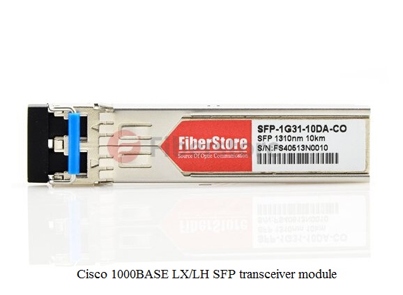
Cisco 1000BASE LX/LH SFP transceiver module

Cisco 1000BASE-T SFP—Cisco GLC-T
The Cisco GLC-T is compliant with the Gigabit Ethernet and 1000BASE-T standards as specified in IEEE STD 802.3 and 802.3ab. Cisco GLC-T operates on standard Category 5 unshielded twisted-pair copper cabling of link lengths up to 100 m (328 ft). It supports RJ-45 connector. Moreover, Cisco GLC-T has low power dissipation (1.05 W typical). The operating temperature range of Cisco GLC-T is 0 to 70°C.

Cisco1000BASE-SX SFP—GLC-SX-MMD
The GLC-SX-MMD, compatible with the IEEE 802.3z 1000BASE-SX standard, operates on legacy 50 μm multi-mode fiber links up to 550 m and on 62.5 μm fiber distributed data interface (FDDI)-grade multi-mode fibers up to 220 m. It can support up to 1km over laser-optimized 50 μm multi-mode fiber cable. And GLC-SX-MMD could be connected with dual LC/PC connector. The average output power is -9.5~ -3dBm and receiver sensitivity is -17dBm. Its operating temperature range is -5 to 85°C.

Cisco1000BASE-LX/LH SFP—GLC-LH-SMD
The GLC-LH-SMD, compatible with the IEEE 802.3z 1000BASE-LX standard, operates on standard single-mode fiber-optic link spans of up to 10km and up to 550m on any multi-mode fibers. It is joint with dual LC/PC connector. And the transmit and receive wavelength ranges from 1270nm to 1355nm. The average output power of GLC-LH-SMD is -9.5~ -3dBm, too. However, the receiver sensitivity is -21dBm.

As stated above, Cisco GLC-T, GLC-SX-MMD and GLC-LH-SMD can be applied under Gigabit Ethernet and have their own features. If you are looking for all or one of them, Fiberstore is an excellent choice. Fiberstore provides fine Cisco GLC-T, GLC-SX-MMD, GLC-LH-SMD and many other SFP modules at very reasonable price.