2015年12月28日星期一

FTTH Access Network Based on GPON

Growing demand for high speed internet drives the new access technologies which enable experiencing true broadband. This leads telecommunication operators to seriously consider the high volume roll-out of optical fiber based access networks. In order to allow faster connections, the optical fiber gets closer and closer to the subscriber. Then FTTH (Fiber To The Home) appears the most suitable choice for a long term objective because it will be easier to increase the bandwidth in the future if the clients are wholly served by optical fibers. FTTH is a future-proof solution for providing broadband services.

Passive optical network (PON) based FTTH access network is a point-to-multipoint, fiber to the premises network architecture in which unpowered optical splitters are used to enable a single optical fiber to serve multiple premises, typically 32-128. The GPON FTTH access network is highly emphasized in this article.

Components of GPON FTTH Access Network

Taking advantages of WDM (wavelength division multiplexing), PON uses one wavelength for downstream traffic and another for upstream traffic on a single fiber. The OLT (Optical Line Terminal) is the main element of the network. Placed in the Local Exchange, OLT is the engine that drives FTTH system. OLT performs the function of traffic scheduling, buffer control and bandwidth allocation. The optical splitter splits the power of the signal and enables sharing of each fiber by many users. ONT (Optical Network Terminal) is deployed at customer’s premises and connected to the OLT through optical fiber and no active elements are present in the link.

GPON FTTH Access Network Architecture

With a tree topology, GPON is able to maximize the coverage with minimum network splits, thus reducing optical power. A FTTH access network comprises five areas, namely a core network area, a central office area, a feeder area, a distribution area and a user area as shown in the following diagram.
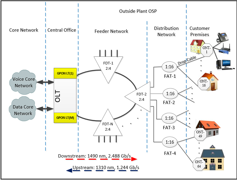
GPON FTTH access network

The core network includes the ISP (internet service provider) equipment, PSTN (packet switched or the legacy circuit switched) and cable TV provider equipment. The main function of the central office is to host the OLT and ODF and provide the necessary powering. The feeder area extends from ODF (optical distribution frames) in the CO (central office) to the distribution points. Distribution cable connects level-1 splitter with level-2 splitter. Level-2 splitter is usually hosted in a pole mounted box placed at the entrance of the neighborhood. In the user area, drop cables are used to connect the level-2 splitter to the subscriber premises.

Traffic Flow in GPON FTTH Access Network

The data is transmitted from OLT to ONT in downstream as a broadcast manner and as a time division multiplexing (TDM) in upstream. The wavelength of the downstream data is 1490 nm. Core network data services transported over the optical network reaches the OLT and then distributed to the ONTs through the FTTH network by dint of power splitting. Every home receives the packets intended to it through its ONT. The upstream represents the data transmission from the ONT to OLT and the wavelength is 1310 nm. If the signals from different ONTs arrive at the splitter input at the same time and at the wavelength 1310 nm, it will lead to superposition of different ONT signals when it reaches OLT. Thus TDMA is adopted to avoid the interference of signals from ONTs. In TDMA time slots will be provided to each user on demand for transmission of their packets. At the optical splitter packets arrive in order and they are combined and transmitted to OLT.

Conclusion

This paper presents the components, architecture, and traffic flow in GPON FTTH access network. The content may not be detailed, but GPON FTTH network architecture is indeed reliable, scalable, and secure. It is a passive network, so there are no active components from the CO to the end user, which dramatically minimizes the network maintenance cost and requirements. It is a future-proof architecture.

Article source: www.fiberopticshare.com/ftth-access-network-based-on-gpon-2.html
2015年12月16日星期三

Introduction to PON Technologies

Passive optical network (PON) is a very significant class of fiber access system in the world and it enjoys a dominant position in the access market. GPON and EPON are the two classifications of PON. The primary differences between the GPON and EPON lie in the protocols used for upstream and downstream communications. This article will introduce PON, GPON and EPON sequentially.

Passive Optical Networks (PON)
 
A PON is a fiber network that only uses fiber and passive components like PON splitters and combiners rather than active components like amplifiers, repeaters, or shaping circuits. Thus PON network costs significantly less than those using active components, but it has a shorter range of coverage limited by signal strength. An active optical network (AON) is able to cover a range to about 100 km (62 miles), while a PON is typically limited to fiber cable runs of up to 20 km (12 miles). PON is also called FTTH (fiber to the home) network.

The typical PON arrangement is a point to multi-point (P2MP) network where a central optical line terminal (OLT) at the service provider’s facility distributes TV or Internet service to as many as 16 to 128 customers per fiber line. Dividing a single optical signal into multiple equal but lower-power signals, the optical splitters distribute the signals to users. An ONU (optical network unit) terminates the PON at the customer’s home. Usually, ONU communicates with ONT (optical network terminal). The ONU/ONT may be one device.

Gigabit Passive Optical Networks (GPON)
 
GPON utilizes optical wavelength division multiplexing (WDM) so a single fiber could be used for both upstream and downstream data. A laser on a wavelength of 1490 nm transmits downstream data, while upstream data transmits on a wavelength of 1310 nm.

While each ONU gets the full downstream rate of 2.488 Gbits/s, GPON uses a time division multiple access (TDMA) format to allocate a specific timeslot to each user. It divides the bandwidth, so each user gets a fraction such as 100 Mbits/s depending on the way the service provider allocates it. The upstream rate is less than the maximum as it is shared with other ONUs in a TDMA scheme. The distance and time delay of each subscriber are determined by the OLT. Then software provides a way to allot timeslots to upstream data for each user. The typical split of a single fiber is 1:32 or 1:64, which means each fiber can serve up to 32 or 64 subscribers. Split ratios up to 1:128 are possible in some systems.

Ethernet Passive Optical Networks (EPON)
 
Based on the Ethernet standard 802.3, EPON 802.3ah specifies a similar passive optical network with a range up to 20 km. EPON uses WDM with the same optical frequencies as GPON and TDMA. The raw line data rate is 1.25 Gbits/s in both the upstream and downstream directions.

EPON technology provides bidirectional 1Gb/s links using 1490nm wavelength for downstream and 1310nm wavelength for upstream, with 1550nm wavelength reserved for future extensions or additional services. EPON is fully compatible with other Ethernet standards, so no encapsulation or conversion is necessary when connecting to Ethernet-based networks on either end. The same Ethernet frame is used with a payload for up to 1518 bytes. As Ethernet is the primary networking technology utilized in local area networks (LAN) and now in metro area networks (MAN), no protocol conversion is needed.

Summary
 
PONs are used to provide triple-play services including TV, and Internet service to subscribers. The lower cost of passive components means simpler systems with fewer components failing or requiring maintenance. The primary disadvantage is shorter range possible, commonly no more than 12 miles or 20 kilometers. As the demand for faster Internet service and more video grows, PONs are growing in popularity. The age of PON has begun. It is a new era of access network upon us.

Article source: www.fiberopticshare.com/introduction-to-pon-technologies.html

2015年12月7日星期一

Things You Should Know about Fiber Optic Connector Polishing

Optical fiber is utilized for high-speed and error-free data transmission across connector assemblies. So the connector end faces need to be polished to optimize performance. And also the connectors must follow acceptance criteria related to insertion and back reflection loss as well as end-face geometry specifications. This article will talk about the fiber optic connectors polishing.

Polishing Process 
 
Early physical contact connectors required spherical forming of their flat end faces as part of the polishing procedure. It involved a four-step process: epoxy removal, ferrule forming, and preliminary and final polishing. These steps utilized aggressive materials for epoxy removal and ferrule forming, generally accomplished with diamond polishing films. Now the polishing process has developed into a sequence of epoxy removal, followed by rough, intermediate and final polishing cycles because almost all connectors are manufactured with a pre-radiused end face. One goal is to avoid excessive disruption of the spherical surface, while still producing a good mating surface.

Polishing Specifications
 
Polishing specifications for fiber connectors fall into two categories related to performance and end-face geometry. Back reflection and insertion loss specifications are the most critical measures of polished end functionality. The insertion loss is the amount of optical power lost at the interface between the connectors caused by fiber misalignment, separation between connections (the air gap) and the finish quality of each connector end. The current standard loss specification is less than 0.5 dB, but less than 0.3 dB is increasingly specified. Back reflection is the light reflected back through the fiber toward the source. High back reflection can translate to signal distortion and, therefore, bit errors in systems with high data transfer rates.

Polishing Material
 
Today several types of connectorized fibers are available, the most common of which are 2.5 mm, 1.25 mm and multifiber. Connector end faces must first be air-polished to ensure a proper mating surface. This will be followed by a sequence of polishing steps depending on the type of connector, the back reflection and the insertion loss specifications. Regardless of the connector type, most polishing sequences begin with aggressive materials, including silicon carbide to remove epoxy and diamond lapping films for beginning and intermediate polishing. These remove both surrounding material and fiber at the same rate. But the last polishing step needs a less aggressive material to attack only the fiber, such as silicon dioxide. Using a material for final polishing that is too aggressive could result in excessive undercut. The wrong final-polish material can cause excessive protrusion, leading to fiber chipping and cracking during the connector mating process.

Impact Factor
 
Issues to be examined include the polishing films used, the type of epoxy and lubrication. Films are the most significant impact because the gradations and quality vary from supplier to supplier. End users should pay attention on selecting film type. Excessively aggressive films can destroy a 125-μm fiber and the end-face radius. Epoxy removal is also essential to contamination-free polishing. Some types of epoxies can be removed more easily with specific grades of silicon-carbide polishing films. The films to use in this step depend on the size of the epoxy bead mounted on the connector end face and the epoxy type. Epoxies have different varieties. Some will be tacky, some firm. In all, a contamination-free environment is essential to optimizing connector polishing.

Polishing may be an old art form, but for the immediate future, it’s here to stay. Undoubtedly inspection criteria will increase. Polishing procedures will be driven to change, and new connector style will also make us continuously strive to reinvent our approach to polishing. Fiberstore has various products about fiber optic polishing. For more details, please visit FS.COM.

Article source: www.fiber-optic-components.com/things-your-should-know-about-fiber-optic-connector-polishing.html

2015年12月1日星期二

Evolution of Flat, PC, UPC and APC Fiber Connectors

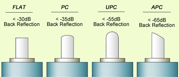
When a connector is installed on the fiber end, loss will be incurred. Some light loss would be reflected back directly down the fiber towards the light source that generated it. These back reflections, or Optical Return Loss (ORL) will damage the laser light sources and also disrupt the transmitted signal. Fiber connectors with different polishing types have different back reflections (see the picture below). With the development of technology, four polishing types are available: flat-surface, Physical Contact (PC), Ultra Physical Contact (UPC), and Angled Physical Contact (APC). How one evolves into another? This article will tell the answer.

polishing type
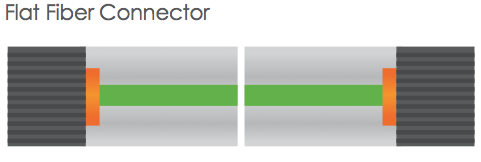
Flat Fiber Connector
The original fiber connector is a flat-surface connection, or a flat fiber connector. The primary issue of it is that a small air gap between the two ferrules is naturally left when mated. This is partly because the relatively large end-face of the connector allows for numerous slight but significant imperfections to gather on the surface. The flat fiber connector is not suitable for single-mode fiber cables with a 9µm core size, thus it is essential to evolve into Physical Contact (PC) connectors.

flat fiber connector
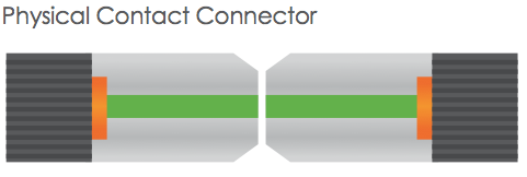
PC Fiber Connector
The Physical Contact is polished with a slight spherical design to reduce the overall size of the end-face, which helps to decrease the air gap issue faced by Flat Fiber connectors. It results in lower Optical Return Loss (ORL) with less light being sent back towards the power source.

PC connector
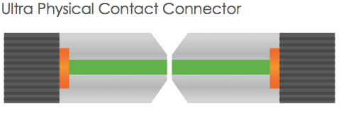
UPC Fiber Connector
Building on the convex end-face attributes of the PC, but utilizing an extended polishing method creates an even finer fiber surface finish: Ultra Physical Contact (UPC) connector. It has a lower back reflection (ORL) than a standard PC connector and allows more reliable signals in digital TV, telephony and data systems. UPC fiber connector could be used with both single-mode fiber and multimode fiber. Usually the UPC single-mode fiber connector is blue, but the UPC multimode fiber connector is beige. (Note: 10G UPC multimode fiber connector is aqua.)

UPC connector

PC and UPC connectors do have a low insertion loss, but the back reflection (ORL) depends on the the surface finish of the fiber. The finer the fiber grain structure, the lower the back reflection. When PC and UPC connectors are continually mated and unmated, the back reflection will begin to degrade. So there is a need for a connector with low back reflection and it could sustain repeated matings/unmatings without ORL degradation.

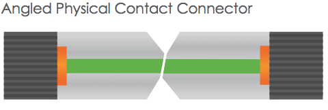
APC Fiber Connector
The end faces of Angled Physical Contact connectors are still curved but are angled at an industry standard eight degrees, which allows for even tighter connections and smaller end-face radii. Combined with that, any light that is redirected back towards the source is actually reflected out into the fiber cladding, again by the virtue of the 8°angled end-face. APC connector back reflection does not degrade with repeated matings/unmatings. APC fiber connector can only be used with single-mode fiber and it is green.

APC connector

It is clear that all of the connector end-face options mentioned above take a place in the market. And it is hard to claim that one connector beats the others when your specification needs to consider cost and simplicity not just optical performance. Your particular need decides which one to choose. For those applications calling for high precision optical fiber signaling, APC should be the first consideration, but less sensitive digital systems will perform equally well using UPC. For various connector options, please visit FS.COM.

Article source: www.fiber-optic-components.com/evolution-of-flat-pc-upc-and-apc-fiber-connectors.html

2015年11月24日星期二

A Guide to Fiber Optic Splicing

Fiber Optic Splicing Basis
 
It is vital for any company or fiber optic technician involved in telecommunications to grasp knowledge of fiber optic splicing methods. Fiber optic splicing refers to joining two fiber optic cables together. It can result in lower light loss and back reflection. Two methods of fiber optic splicing are available: fusion splicing and mechanical splicing. Which technique best fits your economic and performance objectives? Keep reading the following statement and find the answer.

Fusion Splicing vs. Mechanical Splicing
 
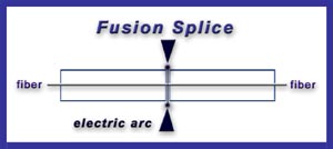
Fusion splicing is an optical junction of two optical fibers by permanently welding them together with heat generated by an electronic arc (called arc fusion). It is the most widely used method of splicing because it provides least reflectance and lowest loss, as well as providing the strongest and most reliable joint between two fibers.

fusion splicing

Fusion splicing steps:
  1. Prepare the fiber: strip the protective coatings, jackets, tubes, strength members, and leave only the bare fiber showing. Pay attention to cleanliness.
  2. Cleave the fiber: using a good fiber optic cleaver here is essential to a successful fusion splice. The cleaved end must be mirror-smooth and perpendicular to the fiber axis to obtain a proper splice.
  3. Fuse the fiber: alignment and heating are the two steps within this step. Alignment can be automatic or manual depending upon the equipment you have. Once the fusion splicer unit are properly aligned, then you can use an electrical arc to melt the fibers and permanently weld the two fiber ends together.
  4. Protect the fiber: protecting the fiber from bending and tensile forces will ensure the splice not break during normal handling. Using heat shrink tubing, silicone gel and/or mechanical crimp protectors will keep the splice protected from outside elements and breakage.
Aligning and holding in place by a self-contained assembly, a mechanical splice is a junction of two or more optical fibers. Not permanently joined, the fibers are just precisely held together so that light can pass from one to another.

mechanical splicing

Mechanical splicing steps:
  1. Prepare the fiber: same with the step of fusion splicing.
  2. Cleave the fiber: the process is identical to the cleaving for fusion splicing.
  3. Mechanically join the fibers: simply position the fiber ends together inside the mechanical splice unit. The index matching gel inside the mechanical splice apparatus will help couple the light from one fiber end to the other.
  4. Protect the fiber: the completed mechanical splice will provide its own protection for the splice.
Tips for Better Splicing
 
  1. Clean your splicing tools thoroughly and frequently.
  2. Operate and maintain your cleaver properly.
  3. For fusion splicing, the fusion parameters must be adjusted minimally and methodically.
Which Method Is Better?
 
Cost and performance are the two deciding factors for choosing one method over the other. Mechanical splicing has a low initial investment ($1,000 - $2,000) but costs more per splice ($12-$40 each). Fusion splicing has lower cost per splice ($0.50 - $1.50 each) but higher initial investment ($15,000 - $50,000). As for the performance, fusion splicing produces lower loss and less back reflection than mechanical splicing. Fusion splices are primarily used with single-mode fiber, while mechanical splices work with both single-mode and multimode fiber.

Conclusion
 
To sum up, the two fiber optic splicing methods have its own advantages. Fusion splicing is invested for long haul single-mode networks, while mechanical splicing is used for shorter local cable runs. For better fiber optic splicing, besides the above splicing steps, high-quality fiber optic splicing tools are also essential, such as fusion splicers, fiber optic cleavers, etc. After all, good methods and excellent tools will produce the best performance.

Originally published: www.fiber-optic-components.com/a-guide-to-fiber-optic-splicing.html

2015年11月17日星期二

How to Optimize Data Center?

When talking about optimizing data center, what you actually want to know is a paradigm shift to a more cost-effective approach to IT data services. Data center optimization is the process of programming and increasing the efficiency of an enterprise’s data center operations. It can help to save your money and time as well as make your technology infrastructure more efficient. Good data center optimization is the difference between sprawling data, compute, and infrastructure spread out across multiple servers and ideal tight clusters, ready to be acted on. But how to optimize your data center? This is a question. Keep reading this article, and then you will get an answer.

Consolidation
 
Servers, storage, network and management — software defined and expertly integrated to save time and money is the latest trend in the data center. Consolidation is able to maximize resources, reduce footprint and save money by optimizing your computing, data, workload, automation and orchestration efforts.

Virtualization
 
Virtualization is about maximizing returns with minimal resources. Release your data center from the confines of the physical and abstract it into a virtual environment, then compose these virtual assets into a solution that makes your business run better.

Data Monitoring and Management
 
It is possible to gain end-to-end visibility of your crucial business processes, application and infrastructure. By using an intuitive user interface, you can monitor and manage your organization’s IT from one dashboard, which makes it much more easier to control what is happening in the infrastructure. Full visibility refers to the ability to predict problem before happening, and then you can make the necessary changes to free up or add necessary resources. Instead of relying on your Help Desk as the first line of error reporting, know that it’s happening ahead of time and have the problem fixed before it becomes an issue.

Automation and Orchestration
 
Free up your knowledge workers from the burden of busy work by automating and orchestrating the most repetitive parts of your workload. Automation and orchestration can help to reduce human errors. Then you can get back to focusing on what really matters. Streamline your processes, and discard the irrelevant ones, potentially outsourcing entire workflows to a policy-based automation. Orchestrate your data center into simplicity and efficiency.

Cloud Workload Migration
 
Cloud workload migration can help to optimize resources and improve performance efficiency. You need to understand what workloads are best moved to the cloud and how to move them efficiently and safely.

Push Yourself as Hard as You Push Your Data
 
You can take your IT and business decisions to a higher level by using your data efficiently. Ask some tough questions that will help to make you more competitive and efficient, and then task your data professionals and IT department with providing the right answers. Finally, scale your questions so that you are pushing yourself and your data to new levels of operational efficiency.

From the above statement, have you got some ideas about how to get your data center optimized? FS.COM is a professional supplier of optical products, such as 10G SFP+, 40G/100G transceiver, etc. It is a wise choice to select data center products from Fiberstore to fill your data center operation system.

Originally published: www.fiber-optic-components.com/how-to-optimize-data-center.html

2015年11月10日星期二

Why Is Fiber Cleaning Necessary?

At a BICSI Conference in 2008, JDSU stated, “Contamination is the number-one reason for troubleshooting optical networks.” For the long-term reliability of any network, fiber cleaning is critical and it is at the heart of the profitability of successful fiber deployment. This paper will introduce the necessity of fiber cleaning and then give two tips on fiber protection against dust contamination.

Four reasons for fiber cleaning are listed below:

Signal Failure
As you know, fiber optic networks work by carrying pulses of light between transmitters and receivers. Contamination and dirt will block the signal and lead to light loss, reducing power and efficiency. The amount of light loss shrinks correspondingly as links carry higher data rates, which makes cleaning even more essential. Dirty equipment can give rise to network failure or paralysis.

Equipment Failure
Dirt can cause permanent damage to the end-face, digging into the surface and creating pits that increase back reflection. Failures in the network caused by dirt can increase costs and install time because damaged equipment may need to be tracked down and replaced, which means more time on-site and greater expenditure. Both of the two will impact the overall budget for a deployment.

Angry Occupants
It is naturally going to enrage consumers and building owners by leaving a mess in a subscriber’s home or the common areas of an apartment building. They’d like to have the benefits of fiber broadband rather than the dirt or damage to their property when it is installed.

Adopting Proper Cleanliness Procedures
While it is easy to focus on more visible debris, dirt is most dangerous at a microscopic level, particularly when it comes to the end-faces of connectors. For example, simply touching the ferrules of a connector will deposit significant amounts of body oil onto the end face. Best practice for this issue is to use high-grade, completely lint-free wipes (aiming for clean room quality) and pure Isopropyl Alcohol (IPA).

On top of this, here are two areas to keep an especially close eye on:

Mating and Unmating
The actual process of mating and unmating connectors can also cause damage to the ceramic. Therefore, aim to minimize this plugging and unplugging as much as possible and ensure you inspect the two end-faces for dirt or debris that could be crushed between them. This can cause permanent damage, such as scratches, cracks or pits that will require re-termination, not just cleaning. Moreover, make sure you inspect any other equipment ports that the connector is being plugged into, as they can also harbour contamination.

Don’t Rely on Dust Caps
Many people may think that if you don’t take the dust cap off your factory terminated connector until you plug it in, it’ll keep dirt free. After all, it was packaged in a sterile factory environment. In fact, dust caps are preventing damage to the end-face, rather than stopping all contamination reaching the connector.

Fiberstore Fiber Cleaning Solution
As a professional supplier in the optical industry, Fiberstore has various high-quality and low-price fiber optic cleaning tools, such as fiber connector cleaner, optical connector cleaning cards, one click fiber optic cleaner for 1.25mm connectors, etc. These tools can help to ease or remove all kinds of dirty particles, such as dust, dripping and moist. Choosing any kind of fiber optic cleaning tools in Fiberstore will give you a surprise!

2015年11月3日星期二

SFP+ Transceiver Testing – TWDPc Measurement

SFP+ transceiver is widely deployed in applications and becomes much more pervasive due to its smaller form factor, less power consumption and its increased port density compared with XFP transceiver. Each SFP+ transceiver houses an optical receiver and transmitter. One end of the transceiver is an optical connection complying with the 10GbE and 8GFC standards, while the other end is an SERDES framer interface (SFI) serial interconnect handling differential signals up to 10 Gbit/s. In order to keep a SFP+ transceiver achieving high performance, the engineers need to acquaint with the key challenges related to testing SFP+ transceiver. This article will first walk through the SFP+ testing challenges and then focus on one kind of testing measurement.

SFP+ Testing Challenges
  • One obvious challenge is the increased port density and the testing time required with 48 or more ports per rack.
  • Another challenge is moving seamlessly from a compliance environment to a debug environment.
  • Yet another problem most designers face today relates to connectivity: how to get the signal out from the device under test (DUT) to an oscilloscope.
  • Another challenge to prepare for is that the SFP+ specification calls out some measurements to be performed using a PRBS31 signal.
  • Additionally, acquiring a record length of 200 million data points demands huge processing power and time.
TWDPc Measurement

TWDPc, short for transmitter waveform distortion penalty for copper, requires a special algorithm defined by the SFP+ specification. This test is defined as a measure of the deterministic dispersion penalty due to a particular transmitter with reference to the emulated multimode fibers and a well-characterized receiver.

TWDPc-measurement

The TWDPc script (of 802.3aq, 10GBASE-LRM) processes a PRBS9 pattern requiring at least 16 samples per unit interval. Out of concern for the large installed base of equivalent-time oscilloscopes with a record length of around 4000 samples, the requirement for 16 samples per unit interval was relaxed to seven samples per unit interval.

The relaxation of the requirement from 16 samples per unit interval to just seven samples per unit interval causes worst-case pessimism of 0.24 dB TWDPc over 30 measurements. For DUTs that already have a high TWDPc, 0.24 dB can be the difference between a pass or a fail result.

The TWDPc measurement for SFP+ host transmitter output specifications for copper requires more than 70 Gsamples/s to capture a minimum of seven samples per UI. Real-time oscilloscopes offering higher sampling rates of 100 Gsamples/s or greater have a much higher chance of providing accurate results for TWDPc compared to scopes that only offer lower sampling-rate options.

Across the board, it is important to map the SFP+ signal’s data-transfer rate to the proper oscilloscope bandwidth requirements to ensure accuracy in measurement and margin testing. With a 10.3125-Gbyte/s data-transfer rate and minimum rise time of 34 ps, a scope with a bandwidth of 16 GHz or higher is required to meet the minimum requirements for SFP+. As noted, sampling rate is also an important consideration for the TWDPc measurement.

Conclusion

Although SFP+ transceiver simplifies the functionality of the 10G optical module, it introduces some test and measurement challenges. TWDPc is a key test for SFP+ transceiver. It defines the differences (in dB) between a reference signal and noise ratio (SNR) and the equivalent SNR at the slicer input of a reference equalizer receiver for the measurement waveform after propagating through a stimulus channel. For SFP+ compliance testing, TWDPc is a required measurement.

2015年10月27日星期二

Data Center 10 Gigabit Ethernet Cabling Options

With the dramatic growth in data center throughput, the usage and demand for higher-performance servers, storage and interconnects have also increased. As a result, the expansion of higher speed Ethernet solutions, especially 10 and 40 Gigabit Ethernet has been ongoing. For 10 Gigabit Ethernet solution, selecting the appropriate 10-gigabit physical media is a challenge, because 10GbE is offered in two broad categories: optical and copper. This article will introduce both optical and copper cabling options for 10 Gigabit Ethernet.

Fiber Optic Cables

Two general types of fiber optic cables are available: single-mode fiber and multimode fiber.

Single-mode Fiber (SMF), typically with an optical core of approximately 9 μm (microns), has lower modal dispersion than multimode fiber. It is able to support distances of at least 10 kilometers, depending on transmission speed, transceivers and the buffer credits allocated in the switches.

Multimode Fiber (MMF), with an optical core of either 50 μm or 62.5 μm, can support distances up to 600 meters, depending on transmission speed and transceivers. 

When planning data center cabling requirements, be sure to consider that a service life of 15-20 years can be expected for fiber optic cabling. Thus the cable chosen should support legacy, current and emerging data rates.

10GBASE-SR — a port type for multimode fiber, 10GBASE-SR cable is the most common type for fiber optic 10GbE cable. It is able to support an SFP+ connector with an optical transceiver rated for 10GbE transmission speed. 10GBASE-SR cable is known as “short reach” fiber optic cable.

10GBASE-LR — a port type for single-mode fiber, 10GBASE-LR cable is the “long reach” fiber optic cable. It is able to support a link length of 10 kilometers.

OM3 and OM4 are multimode cables that are “laser optimized” and support 10GbE applications. The transmission distance can be up to 300 m and 400 m respectively.

Copper Cables

Common forms of 10GbE copper cables are as follows:

10GBASE-CR — the most common type of copper 10GbE cable, 10GBASE-CR cable uses an attached SFP+ connector and it is also known as a SFP+ Direct Attach Copper (DAC). This fits into the same form factor connector and housing as the fiber optic cables with SFP+ connectors. Many 10GbE switches accept cables with SFP+ connectors, which support both copper and fiber optic cables.

Passive and Active DAC — passive copper connections are common with many interfaces. As the transfer rates increase, passive copper does not provide the distance needed and takes up too much physical space. So the industry is moving towards an active copper type of interface for higher speed connections. Active copper connections include components that boost the signal, reduce the noise and work with smaller gauge cables, improving signal distance, cable flexibility and airflow.

10GBASE-T — 10GBASE-T cables are Cat6a (category 6 augmented). Supporting the higher frequencies required for 10GbE transmission, category 6a is required to reach the distance of 100 meters (330 feet). Cables must be certified to at least 500 MHz to ensure 10GBASE-T compliance. Cat 6 cables may work in 10GBASE-T deployments up to 55 meters (180 feet) depending on the quality of installation. Some 10GbE switches support 10GBASE-T (RJ45) connectors.

When to Use Different Type of 10GbE Cables

To summarize, currently the most common types of 10GbE cables use SFP+ connectors.
  • For short distances, such as within a rack or to a nearby rack, use DAC with SFP+ connectors, also known as 10GBASE-CR.
  • For mid-range distances, use laser optimized multimode fiber cables, either OM3 or OM4, with SFP+ connectors.
  • For long-range distances, use single-mode fiber optic cables, also known as 10GBASE-LR. 
Originally published: www.fiber-optic-components.com/data-center-10-gigabit-ethernet-cabling-options.html

2015年10月22日星期四

How to Achieve a Reliable, Affordable and Simple 10 Gigabit Ethernet Deployment?

10 Gigabit Ethernet, or 10GE and 10GbE, is a group of computer networking technologies for transmitting Ethernet frames at a rate of 10 gigabits per second. Nowadays, 10 Gigabit Ethernet is gaining broader deployments by the increasing bandwidth requirements and the growth of enterprise applications. But there is a question to be considered when deploying 10 Gigabit Ethernet — how to achieve a reliable, affordable and simple 10 Gigabit Ethernet deployment? The text below will tell the answer.

10 Gigabit Ethernet and the Server Edge: Better Efficiency

Server virtualization supports several applications and operating systems on a single server by defining multiple virtual machines on the server. Virtual machines grow and require larger amounts of storage than one physical server can provide. Storage area networks (SANs) or network attached storage (NAS) provide additional and dedicated storage for virtual machines. But connectivity between the servers and storage must be fast to avoid bottlenecks. 10 Gigabit Ethernet is able to provide fastest interconnectivity for virtualized environments.

10 Gigabit Ethernet SAN versus Fibre Channel: Simpler and More Cost-effective

The Internet Small Computer System Interface (iSCSI), an extension of SCSI protocol used for block transfers in most storage devices and Fibre Channel, is making 10 Gigabit Ethernet an attractive, alternative interconnect fabric for SAN applications. The iSCSI capabilities allow 10 Gigabit Ethernet to compare very favorably to Fibre Channel as a SAN interconnect fabric. 10GbE networking can reduce equipment and management costs as its components are less expensive than highly specialized Fibre Channel components and do not require a specialized skill set for installation and management.

10 Gigabit Ethernet and the Aggregation Layer: Reduce Bottlenecks

10 Gigabit Ethernet allows the aggregation layer to scale to meet the increasing demands of users and applications. It can help bring oversubscription ratios back in line with network-design best practices, and provides some important advantages over aggregating multiple Gigabit Ethernet link, such as less fiber usage, greater support for large streams and longer deployment lifetimes.

10 Gigabit Ethernet and Fiber Cabling Choices

For any fiber cable deployment, the types of fiber cable, 10 Gigabit Ethernet physical interface and optics module form factor need to be considered. Form factor options are interoperable as long as the 10 Gigabit Ethernet physical interface type is the same on both ends of the fiber link.

10 Gigabit Ethernet and Copper Cabling Choices

Currently, three different copper cabling technologies for 10 Gigabit Ethernet are available. 10GBASE-CX4 was the first 10 Gigabit Ethernet copper standard. CX4 was relatively economical and allowed for very low latency. Its disadvantage was a too-large form factor for high density port counts in aggregation switches. SFP+ direct attach cables (DAC) connect directly into an SFP+ housing. It has become the connectivity of choice for servers and storage devices in a rack due to its low latency, small form factor and reasonable cost. 10GBASE-T is able to run 10 Gigabit Ethernet over CAT6a and CAT7 copper cabling up to 100 meters, but it needs technology improvements to lower its cost, power consumption and latency.

10 Gigabit Ethernet and the SFP+ Makeover: Direct Attach Cables are convenient for Short Runs

SFP+ direct attach cables integrate SFP+ connectors with a copper cable into a low-latency, energy-efficient, and low-cost solution. Direct attach cables are currently the best cabling option for short 10 Gigabit Ethernet connections.

10 Gigabit Ethernet and Link Aggregation Offers Redundancy and Resiliency

The Link Aggregation Control Protocol (LACP) standard defines a way of bundling several physical ports over one logical channel. From a deployment standpoint, it is far easier to implement a distributed LACP solution with stackable switches that allow link aggregation across the stack. In this configuration, the stack acts as a single logical switch and link aggregation is seamless.

10 Gigabit Ethernet and Top-of-Rack Best Practice

The diagram below shows a stackable 10 Gigabit Ethernet ToR switching solution enabling cost-effective SAN connectivity for servers and network storage. In addition to better performance, LACP functionality provides better availability and redundancy for servers and storage. Moreover, it provides failover protection if one physical link goes down, while iSCSI traffic load balancing ensures greater transmission throughput with lower latency.

10GbE ToR switching solution

10 Gigabit Ethernet and Distribution Layer Best Practice

The diagram below shows Gigabit access switches with 10 Gigabit uplinks and stackable 10 Gigabit aggregation switches. At the edge, stacks of access switches are virtualized into a single switch, reducing configuration and management overhead.

Gigabit access switches

To achieve a reliable, affordable and simple 10 Gigabit Ethernet deployment, the factors stated above need to be considered. Fiberstore SFP+ transceivers and SFP+ direct attach cables are ideal for cost-sensitive organizations considering 10 Gigabit Ethernet applications and they help growing companies support rising bandwidth requirements, new applications, and the demands of a fast-paced business environment.

2015年10月14日星期三

Fiberstore Passive Optical Components Solution

Passive optical components market is propelled by the accelerating bandwidth requirements coupled with the growth of passive optical network (PON). Usage of passive optical components to obtain energy efficient network solutions is gaining popularity. This article will introduce some Fiberstore passive optical components.

Optical Attenuators: an optical attenuator is a device that is used to reduce the power level of an optical signal. Optical attenuators are commonly used in fiber optic communications, either to test power level margins by temporarily adding a calibrated amount of signal loss, or installed permanently to properly match transmitter and receiver levels.

optical attenuators

Optical Circulator: an optical circulator is a multi-port (minimum three ports) non-reciprocal passive component. The function of an optical circulator is similar to that of a microwave circulator — to transmit a light wave from one port to the next sequential port with a maximum intensity, but at the same time to block any light transmission from one port to the previous port.

optical circulator

Fiber Collimator: a fiber collimator is a device for collimating the light coming from a fiber, or for launching collimated light into the fiber. It is used to expand and collimate the output light at the fiber end, or to couple light beams between two fibers. Both single-mode fiber collimators and multimode fiber collimators are available.

fiber collimator

Optical Isolator: an optical isolator is a passive optical component that allows light to propagate in only one direction. Optical isolators are typically used to protect light sources from back reflections or signals that can cause instabilities and damage. The operation of optical isolators depends on the Faraday effect, which is used in the main component, the Faraday rotator.

optical isolator

Fiber Optic Sensor: a fiber optic sensor is a sensor that uses optical fiber either as the sensing element (intrinsic sensors), or as a means of relaying signals from a remote sensor to the electronics that process the signals (extrinsic sensors). Fiber optic sensors are immune to electromagnetic interference, and do not conduct electricity so they can be used in places where there is high voltage electricity or flammable material such as jet fuel.

fiber optic sensor

Pump Combiner: a pump combiner is a passive optical component built based on fused biconical taper (FBT) technique. Pump combiners are widely used in fiber laser, fiber amplifier, high power EDFA, biomedical and sensor system etc. Three types of pump combiners are available: Nx1 Multimode Pump Combiner, (N+1)x1 Multimode Pump and Signal Combiner, PM(N+1)x1 PM Pump and Signal Combiner.

pump combiner

Polarization Components: polarization is the state of the e-vector orientation. Polarization components are used to isolate and transmit a single state of polarized light while absorbing, reflecting, and deviating light with the orthogonal state of polarization. Polarization components can be utilized in high power optical amplifiers and optical transmission system, test and measurement.

polarization components

Fiberstore has all of the above passive optical components with high quality and reasonable price. You can select excellent passive optical components or other optical products for your network at www.fs.com.

2015年10月7日星期三

OTDR, LTS and Source&Meter: Which Is Better for You?

As the technology advances further, the kinds of fiber optic testers also have increased. The variety of choices of such devices can be overwhelming to a would-be buyer. This paper will introduce you some common types, such as OTDR (optical time domain reflectometer), LTS (loss test set) and Source & Meter. But there is a problem you should know that the function of them is very similar since they all can be used to test cable installation or outside plant applications. As a result, it would be hard for us to select the right one for detecting our fiber optic events. Under this circumstances, here comes the question: OTDR, LTS and Source&Meter, which is better?

Introduction to OTDR, LTS and Source&Meter

Before you know how to choose the right one from these fiber optic testers, you must have a basic knowledge of them. So next, OTDR (optical time domain reflectometer), LTS (loss test set) and Source & Meter, each of them would be given a brief introduction.

OTDR - OTDR is essentially an optical radar. It sends pulses of light into optical fibers, and then analyzes the minuscule amounts of light which is reflected back to them. Also, complex computations are used to determine the size and distance to events encountered in the fiber run. Events are defined as losses or changes in the fiber’s light-carrying capacity.

OTDR 

LTS - In the heart of the LTS, it is the combination of a power meter and light source. Measurements are made with a two stage process. First the source power is measured, then light is put through the device to be tested, and a second measurement is made. The difference in the measurements is the device loss.

LTS

Source & Meter - Sources and Meters perform the same functions as an LTS. But compared with LTS, it has greater flexibility since a single source and meter pair can also be used at each end of a link.

Source & Meter

OTDR, LTS and Source&Meter: Which Is Better

After knowing about the basic knowledge about these fiber optic testers, there are some features of them you should know so that you can choose the right fiber optic tester for your fiber networks.

Cost - Compared to a loss test set or source & meter, OTDR requires more technical expertise which determines it has higher labor expense. What is more, it has high asset expense and administration expense. So if you plan to use an OTDR frequently, it makes sense to buy one. If not, you had better rent one to reduce cost. As to LTS and Source & Meter, one LTS may be cheaper than a source / meter pair. Because it has less inventory to maintain and deploy, that is why its ongoing costs is lower.

Ease of use - OTDR readings must be analyzed and interpreted by trained and experienced people. It’s difficult for a less qualified installer to operate an OTDR and make sense out of it. As a result, using this device can require considerable time and effort. But LTS is the simplest way to ensure that connections are up to standard, and is widely used by almost everyone involved in hands-on work. Source & Meter is slightly harder to use when compared with LTS in that it does not have some sorts of automated wavelength synchronisation.

Application - OTDR is designed for outside plant (OSP) applications. Most OSP installations involve splicing single-mode fiber to get longer runs and the OTDR allows verifying the quality of the splice. But when that link is finished, it must still be tested for insertion loss with a light source, power meter and reference cables, just like premises cables. Premises cables rarely have splices and are short, often too short for the OTDR to measure. LTS can be used to simply and reliably measure end to end loss of installed systems, preferably using a bi-directional or two-way method at multiple wavelengths, with minimum inventory and modest technician skill levels. The use of Source & Meter is more flexibility. One source & meter can measure a link, whereas two LTS (Loss Test Set) instruments are needed. And a source is not needed to do transmission power measurements, so it can be used elsewhere.

From the above analysis, we can see that the cost of OTDR is the highest, and it is more suitable for experts to use. While the cost of LTS is the lowest, and it s relatively simple to use. Source & Meter is between them. In a word, these fiber optic testers are all indispensable instruments that can illuminate problems in your optical fiber before they bring your system to its knees. Once you are familiar with the features of them, you will be prepared to choose the right one to detect and eliminate your optical fiber events.

2015年9月29日星期二

BiDi Transceiver Overview

For several years ago, when talked about fiber optic transceiver, almost most of people engaged in telecommunication industry would tell that a transceiver is a device comprising both a transmitter and a receiver which are combined and share common circuitry. Almost all fiber optic transceivers uses two fibers to transmit data between routers and switches. One fiber is devoted to transmitting data to the networking equipment, while the other one is devoted to receiving data from the networking equipment. For recent years, a new kind of fiber optic transceiver has been available — Bi-Directional transceiver (BiDi transceiver).

BiDi Transceiver Basis

BiDi transceiver is a type of fiber optic transceiver which uses WDM (wavelength division multiplexing) bi-directional transmission technology so that it can achieve the transmission of optical channels on a fiber propagating simultaneously in both directions. BiDi transceiver is only with one port which uses an integral bidirectional coupler to transmit and receive signals over a single optical fiber (see the following picture). BiDi transceivers are specifically designed for the high-performance integrated duplex data link over a single optical fiber and used in bi-directional communication applications. The BiDi transceivers interface a network device mother board (for a switch, router or similar device) to a fiber optic or unshielded twisted pair networking cable.

BiDi transceiver

Working Principle of BiDi Transceiver

The difference between BiDi transceivers and the two-fiber optical transceiver mainly lies in that BiDi transceivers are fitted with WDM couplers, also known as diplexers, which help to combine and separate data transmitted over a single fiber based on the wavelengths of the light. So BiDi transceivers are also called WDM transceivers. BiDi transceivers are usually deployed in matched pairs to get the work most efficiently. And the diplexers of BiDi transceivers are tuned to match the expected wavelength of the transmitter and receiver that they will be transmitting data from or to.

As can be seen from the following diagram, the paired BiDi transceivers are being used to connect two devices. Device A is used to get upstream data, and Device B is used to get downstream data. Tx means transmit. Rx means receive. The diplexer in one transceiver (Device A) should have a transmitting wavelength of 1310 nm and have a receiving wavelength of 1550 nm. The diplexer in the other transceiver (Device B) should have a transmitting wavelength of 1550 nm and have a receiving wavelength of 1310 nm.

BiDi transceiver

Advantages of BiDi Transceiver

The decisive advantage of using BiDi transceiver is that it helps to reduce the cost of fiber cabling infrastructure. This is caused by reducing the number of fiber path panel ports as well as reducing the amount of tray space dedicated to fiber management. The deployment of BiDi transceiver enables the bandwidth capacity of the optical fiber to be doubled.
 
Fiberstore BiDi Transceiver Solution

Fiberstore supplies a series of BiDi transceivers with different types such as BiDi SFP. These BiDi SFP transceivers support Fast Ethernet, Gigabit Ethernet, and Fibre Channel, etc. And they can be available for simplex SC or LC connector interface, which is used for data transmitting and receiving. Also, the BiDi SFPs from Fiberstore are able to support a wide range of physical media from copper to long-wave single-mode optical fiber with transmission distance up to hundreds of kilometers. The most typical Tx and Rx wavelength combinations are 1310/1490 nm, 1310/1550 nm and 1490/1550 nm. Fiberstore has a large selection of BiDi transceivers in stock. Choosing a Fiberstore BiDi transceiver can help your fiber optic network to be most economical and efficient.

Originally published: www.fiber-optic-components.com/

2015年9月25日星期五

SC Connector Overview

SC connector was developed by the laboratories at Nippon Telegraph and Telephone (NTT) in 1980s, hitting the market strongly after the advent of ceramic ferrules as the first connector. SC stands for “square connector” or “subscriber connector”, which is a push-on, pull-off connector with a locking tab. It has a push-pull coupling end face with a spring loaded ceramic ferrule by which SC connector can provide for accurate alignment. Commonly, it can be used with singlemode and multimode fiber optic cables with low cost, simplicity, and durability. Due to its excellent performance, it dominated fiber optics for over a decade and still plays an important part now.

SC Connector Structure

The picture below has given a visualized description of the most common elements in SC connector. It is mainly made up of the fiber ferrule, connector sub-assembly body, connector housing, fiber cable and stress relief boot.
SC connector structure
The fiber ferrule - In the heart of SC connector, there is a long cylindrical 2.5mm diameter ferrule which is made of ceramic or metal. The ferrule has a hole about 124~127um diameter in its center, so that the stripped bare fiber can be inserted through it. The end of the fiber is at the end of the ferrule, where it typically is polished smooth.

The connector sub-assembly body - The ferrule is then assembled in the SC sub-assembly body. The end of the ferrule protrudes out of the sub-assembly body to mate with another SC connector inside a mating sleeve (also called adapter or coupler).

The connector housing - Connector sub-assembly body is then assembled together with the connector housing. Connector housing provides the mechanism for snapping into a mating sleeve (adapter) and hold the connector in place.


The fiber cable - Fiber cables are often crimped onto the connector sub-assembly body with a crimp eyelet. This provides the strength for mechanical handing of the connector without putting stress on the fiber itself.

The stress relief boot - Stress relief boot covers the joint between connector body and fiber cable, and protects fiber cable from mechanical damage.

SC Connector Types

According to the polish style, SC connector can be divided into PC (Physical Contact) style, UPC (Ultra Physical Contact) style and APC (Angled Physical Contact) style. SC PC connector is polished with a slight spherical (cone) design to reduce the overall size of the end-face. But now, the most common types are UPC type and APC type.

SC UPC connector - It is an improvement from SC PC connector, resulting in a lower back reflection (ORL) than a standard PC connector, and allowing more reliable signals in digital TV, telephony and data systems. It is available in single-mode and multimode. You can tell them apart from the color: SMF UPC connector is blue, while MMF UPC connector is beige.

SC APC connector - It is angled at an industry-standard eight degrees. As a result, any light that is redirected back towards the source is actually reflected out into the fiber cladding, again by virtue of the 8° angled end-face. That is why its back reflection is the lowest among the three types. APC connector is only available in single-mode, and the color of it is green.
SC APC connector and UPC connector

According to the application, SC connector includes SC BTW connector and SC jumper connector.

SC BTW Connectors - BTW is the abbreviation of “behind the wall”. As the name implies, can be used to connect the adapter panel, and then terminate Outside Plant (OSP) cables as well as building cables. SC BTW connectors are designed for 900 micron buffered fiber. This product is intended to meet Telcordia GR-326-CORE, Issue 3 for Type II Media (900 micron buffered fiber).

SC Jumper Connectors - Generally, SC jumper connectors are designed on the end of fiber patch cables, and then connect GBIC modules in Central Office (CO), Local Area Networks (LANs), device terminations, etc. Robust family of connectors designed to mount on 1.6 – 3.0 mm fiber cordage and intended to meet the Telcordia GR-326-CORE, Issue 3, for Type I Media (reinforced jumper cordage). The common types are 2mm Jumper connector and 3mm Jumper connector.

SC Connector Application

Generally, when compared with other connectors, SC connector is more rugged and adaptable. What is more, it is capable of tunable and stable performance. With these significantly features, SC connector can be applied in many fields, such as telecommunication, CATV, broadband and so on. The products of SC connector are also various, such as SC adapters, SC terminators, SC converters and SC jumpers.

Fiberstore Solution

Fiberstore as the main professional fiber optic products manufacturer in china offers a various kinds of fiber cable connectors, including SC Connectors. What is more, the products with these connectors are also full in store, such as SC fiber cable, with good quality and low price.

Article Source: www.chinacablesbuy.com/

2015年9月18日星期五

Guide to Optical Attenuators

Attenuators Overview

An optical attenuator, or fiber optic attenuator, is a device used to reduce the power level of an optical signal, either in free space or in an optical fiber. The optical attenuators can have a tuning control to set the level of attenuation into a range of selectable values (variable optical attenuators), or can introduce a fixed level of attenuation (fixed optical attenuators). 

Variable optical attenuators are normally used for testing and measurement. Also they could be used in EDFAs (erbium doped fiber amplifier) for equalizing the light power among separate channels. Fixed optical attenuators have fixed values specified in decibels. The attenuation is expressed in dB and its value cannot be varied. It is ideal for attenuating single-mode fiber connectors in various applications.

Why Use Optical Attenuators?

Optical attenuators is a critical component of any fiber optic network. Using an attenuator, the transmission signal into the dynamic range of the receiver could be adjusted. This increases the life span of the optical equipment and ultimately provides a clearer transmission signal. Moreover, the utilization of optical attenuators could assure the linear behaviour of optical fiber receivers avoiding optical power overloading. At the same time, it is able to balance the optical power into passive optical network branches and can make measurements on an optical telecommunication system.

How Optical Attenuators Work?

Optical attenuators usually work by absorbing the light, like sunglasses absorb the extra light energy. Typically, they have a working wavelength range in which they absorb the light energy equally. However, they should not reflect the light since that could cause unwanted back reflection in the fiber system. Another type of attenuator utilizes a length of high-loss optical fiber, that operates upon its input optical signal power level in such a way that its output signal power level is less than the input level.

Application of Optical Attenuators

Optical attenuators are commonly used in fiber optic communications. They could be used to test power level margins by temporarily adding a calibrated amount of signal loss, or installed permanently to properly match transmitter and receiver levels. 

One of the important applications of optical attenuators is channel balancing in WDMs (wavelength division multiplexing). As illustrated in the following picture, an eight channel wavelength multiplexed signal from a trunk line is demultiplexed into individual signals. The signals are of different intensities, and need to be balanced to avoid saturating any of the receivers. So each channel is sent through a corresponding port on an eight channel MEMS (micro-electro-mechanical systems) VOA (variable optical attenuator). The signal strength through the optical attenuator outputs is monitored by a control circuit. If the output signal gets too high or too low, the corresponding optical attenuator is adjusted to bring the light level to the correct range.


As stated above, an optical attenuator is used to reduce the power level when there is too much light deliver through a fiber optic receiver. It is used to adjust optical signal levels thereby increasing network flexibility and providing management of optical power. If you are looking for an optical attenuator, Fiberstore is a primary option. It has many different fixed optical attenuators and variable optical attenuators including fixed LC/APC fiber optic attenuator, fixed SC/UPC fiber optic attenuator, BVA610 optical variable attenuator(0-60dB), etc. For more information, you can visit www.fiberstore.com.

2015年9月9日星期三

50µm and 62.5µm Multimode Optical Fiber: Which Is More Preferable?

Multimode optical fiber is a type of optical fiber mainly used for transmission over short distances, such as in a building or on a campus. Typical multimode optical fibers support data rates from 10 Mbps to 10 Gbps over link lengths of up to 600 meters. It can offer reliable, flexible and cost effective cabling solutions for local area networks, central offices and data centers.

What Are 50/125µm and 62.5/125µm Multimode Optical Fiber?

According to the core and cladding diameters, multimode optical fiber can be divided into 50/125 µm and 62.5/125 µm. 50 µm and 62.5 µm refer to the diameters of the fiber core, which is the area that carries light signals. 125 µm means the cladding diameter of the fiber. The cladding confines the light to the core as it has a lower index of refraction. Cable construction is shown in the following diagram indicating the cable core, cladding and outer jacket diameters. Currently, there are four types of multimode optical fibers: 62.5µm multimode optical fiber (OM1), 50µm multimode optical fiber (OM2), laser-optimized 50µm multimode optical fiber (OM3) and laser-optimized 50µm multimode optical fiber (OM4). 

multimode optical fiber

Why Two Core Diameters?

When optical fiber was introduced for 10Mbps and then 100Mbps Ethernet, light-emitting diode (LED) light sources and 62.5µm fiber were used. LEDs overfill the fiber core, so larger core diameters mean more light is collected, and thus data can be carried farther as shown in the following picture A. 

In order to achieve 1Gbps performance, the light source was upgraded to vertical-cavity surface-emitting laser (VCSEL). VCSELs can switch more rapidly than LEDS, which makes them better for higher data rates. Moreover, VCSELs emit much smaller and more sharply focused beams, coupling more power into the fiber for greater efficiency as the following picture B shown. With a VCSEL light source, all of the light is coupled into the fiber, so a larger core diameter does not gather more light. In fact, a larger core diameter transmits the light less efficiently as a result of modal dispersion. Using 50µm fiber decreased modal dispersion and then increased the reach of 1Gbps fiber cabling.

LED and VCSEL

Which Is More Preferable?

62.5µm fiber could support 2km campuses at 10 Mbps because more light for LEDs could be coupled into its larger core. And it dominated the premises market for more than a decade. However, with faster transmission rates and higher bandwidth demands, changing market conditions was imperative. So 50µm fiber has been established as the best solution for applications > 10 Mbps. The 100Mbps Fast Ethernet standard invited the use of LEDs that take advantage of lower fiber attenuation at 1300nm wavelength, which offset the LED coupling loss into 50µm fiber caused by its smaller core diameter. Hence, 50µm fiber could support the same 2km reach at 100 Mbps as 62.5µm fiber.

As data rates rise to Gigabit speeds, 62.5µm fiber is stretched beyond its performance limit because of its lower bandwidth at 850 nm. By contrast, 50µm fiber has as much as ten times the bandwidth of the 62.5µm fiber, which enables support of 1Gbps and 10Gbps applications. As 1Gbps and 10Gbps transmitters use small spot-size lasers, concerns over power coupling efficiency into 50µm fiber are no longer an issue. Moreover, the laser-optimized 50µm multimode optical fiber can offer the most secure and least-cost upgrade path to higher-speed networks as it is able to support 40 and 100Gbps data transmission.

Conclusion

As stated above, 50µm multimode optical fiber is more preferable than 62.5µm multimode optical fiber. Using 50µm multimode optical fiber can bring benefits of faster transmission rates and higher bandwidth. If you have not put 50µm multimode optical fiber into use, it is time to employ 50µm multimode optical fiber for higher performance on your network.

2015年9月1日星期二

Passive Optical Network–A Superior Network Solution

With the explosive growth of Internet, the introduction of a broadband access network based on fiber-to-the-office (FTTO) and fiber-to-the-home (FTTH) has been triggered. Under this circumstance, access and metro networks should be scalable in terms of capacity and accommodation as well as flexible with regard to physical topology. Passive optical network (PON), one class of fiber access system, can deal with the various demands.

Definition

A passive optical network (PON) is a telecommunication network that uses point-to-multipoint fiber to the end-points in which unpowered optical splitters are used to enable a single optical fiber to serve multiple end-points. It consists of an optical line terminal (OLT) at the service provider’s central office and a number of optical network units (ONUs) or optical network terminals (ONTs), near end users (see below figure). PON takes advantages of wavelength division multiplexing (WDM) and uses one optical wavelength for upstream traffic while another for downstream traffic on a single-mode fiber. The upstream signals are combined at the splitters by using a multiple access protocol (time division multiple access). The downstream signals are directed to multiple users by passive optical splitter technology.

passive optical network

Advantages

There are two ways that the signals can be broken out in shared fiber architectures. One is active Ethernet (AE), with which the individual signals are split out using electronic equipment near the subscriber. The other one is PON, in which the signals are replicated passively by the splitter. Compared with AE, a network based on a PON system is more superior. The advantages of PON are as below.

PON incurs lower capital expenditures because it has no electronic components in the field. Also PON lowers the operational expenditures as there is no need for the operators to provide and monitor electrical power in the field or maintain backup batteries. Besides, a PON has a higher reliability because in the PON outside plant there are no electronic components which are prone to failure. Additionally, one of the most crucial features of a PON-based access network is its signal rate and format transparency. It is much simpler for a PON to upgrade to higher bit rates. Both AE and PON require upgraded electronics in the CO and customer premises, but unlike AE, PON does not need to upgrade in the outside plant as the passive splitters are agnostic to PON speed. Lastly, a PON solution has the ability to span long distances without degrading performance. The low-loss characteristics of single-mode fiber enable PON to support a maximum physical reach of 20 kilometers.

Applications

There are some applications for which PON is well suited, such as fiber-to-the-home (FTTH) delivery of voice, Internet data, and cable access broadband video. More specifically, PON is used when the applications require anticipated system to upgrade to high-security areas or where the rerouting of cable may be difficult. Or in the cases that installations involving widely dispersed nodes require long runs of fiber. And PON is utilized for the projects where costs, especially initial deployment costs, are a key concern. At the same time, using PON can help user bandwidth to be adequately managed.

By reading the above illustration, have you got a basic understanding about the passive optical network? Fiberstore, a professional manufacturer and supplier in the optical industry, has many high-quality PON products including PON splitters, optical network units and optical line terminal. Choosing a PON product in Fiberstore can help to deploy your network more efficiently.

Originally published: www.fiber-optic-components.com/passive-optical-network-a-superior-network-solution.html