2016年8月31日星期三

24-Fiber Trunk Cabling – A Better Solution for 10-40-100G Migration

In the data centers, tremendous amount of business data needs to be transmitted, processed and stored. Fiber optic links are vital for providing the bandwidth and speed needed to transmit huge amounts of data to and from a large number of sources. Transmission speeds at core switches are increasing and backbone infrastructures are experiencing a significant upsurge in the amount of fiber optic cabling. The 24-fiber trunking and interconnect solution, allowing enterprise data center managers to effectively migrate from 10G to 40/100G, offers the right 10-40-100G migration path. Why say so? Keep reading and you will find the answer.

Standards of 40G and 100G

The IEEE ratified the 802.3ae standard for 10G over fiber using duplex-fiber links (one for transmitting and the other for receiving) in 2002. In 2010, the IEEE ratified the 802.3ba standard for 40G and 100G by using parallel optics, or multiple lanes of fiber transmitting at the same speed. Running 40G requires 8 fibers, with 4 fibers each transmitting at 10G and 4 fibers each receiving at 10G, while running 100G requires a total of 20 fibers, with 10 transmitting at 10G and 10 receiving at 10G. Both scenarios call for high-density multi-fiber MPO connectors.

MPO Connectors and Cables for 40G and 100G

For 40G, a 12-fiber MPO connector is used. Because only 8 optical fibers are required, typical 40G applications use only the 4 left and 4 right optical fibers of the 12-fiber MPO connector, while the inner 4 optical fibers are left unused. To run 100G, a 24-fiber MPO connector is recommended, with the 20 fibers in the middle of the connector transmitting and receiving at 10G and the 2 top and bottom fibers on the left and right unused.
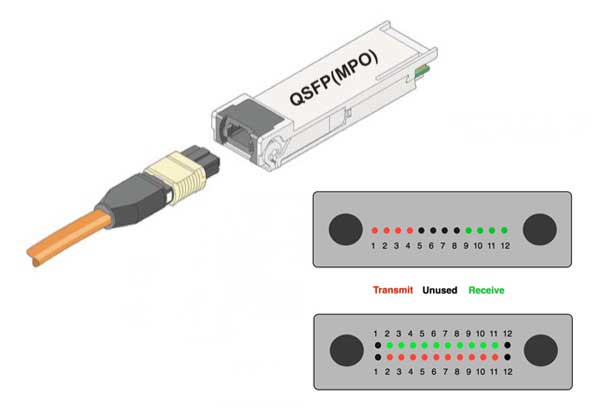
MPO connector


According to the IEEE 802.3ba standard, multimode optical fiber supports both 40G and 100G over link lengths up to 150 meters while using OM4 optical fiber and up to 100 meters when using OM3 optical fiber. It is important to note that single-mode fiber can also be used for running 40G and 100G to much greater distances using wavelength division multiplexing (WDM). While this is ideal for longer-reach applications, for most data center applications of less than 150 meters, single-mode fiber are not feasible due to expensive costs. Copper twinax cable is also capable of supporting 40G and 100G but only to distances of 7 meters.

Why Does 24-Fiber Trunk Cable Provide a Better Migration Path?

The use of 24-fiber trunk cables can support 10G, 40G and 100G applications. For 10G applications, each of the 24 fibers can be used to transmit 10G, for a total of 12 links. For 40G applications, which requires 8 fibers (4 transmitting and 4 receiving), a 24-fiber trunk cable provides a total of three 40G links. For 100G, which requires 20 fibers (10 transmitting and 10 receiving), a 24-fiber trunk cable provides a single 100G link. Some benefits of using 24-fiber trunk cables are listed below.

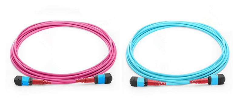
24 fiber MTP/MPO trunk cables
  • Maximum Fiber Use
As mentioned previously, 40G uses 8 fibers of a 12-fiber MPO, leaving 4 fibers unused. When using a 12-fiber trunk cable, those same 4 fibers are unused. For example, three 40G links using three separate 12-fiber trunk cables would result in a total of 12 unused fibers, or 4 fibers unused for each trunk. With the use of 24-fiber trunk cables, data center managers actually get to use all the fiber and leverage their complete investment. Running three, 40G links over a single 24-fiber trunk cable uses all 24 fibers of the trunk cable. This recoups 33% of the fibers that would be lost with 12-fiber trunk cables, providing a much better return on investment.
  • Reduced Cable Congestion
Less cable congestion in already-crowded pathways is another benefit of 24-fiber trunk cable. Space is premium in the data center, and congested cable pathways can make cable management more difficult and impede proper airflow needed to maintain efficient cooling and subsequent energy efficiency. The 24-fiber trunk cables are appreciably larger than 12-fiber trunk cables. For a 40G application, it takes three 12-fiber trunk cables to provide the same number of links as a single 24-fiber trunk cable, which may need 1.5 times more pathway space.
  • Easier Migration Path
The 24-fiber data center fiber trunking and interconnect solution offers a simple and cost-effective migration path from 10G to 40G and 100G. With 24-fiber trunk cables effectively supporting all three applications, upgrading the cabling infrastructure is as simple as upgrading the hydra cables or cassettes and patch cords to the equipment.

Conclusion

The 24-fiber data center trunking and interconnect solution helps data center managers effectively and efficiently support today’s high-speed requirements. With 24-fiber trunk cables that eliminate the need for complete and complex reconfiguration all the way from the switch to the equipment, it offers an easy, cost-effective method for upgrading from 10G, to 40G and 100G with the least capital and operating expense.


2016年8月17日星期三

FS.COM LC Fiber Patch Cables Solution

Fiber optic patch cables, also called fiber optic patch cords or fiber jumpers, are composed of fiber optic cables terminated with fiber optic connectors on both ends. They are designed to interconnect or cross connect fiber networks within structured cabling systems. Various types of fiber jumpers can be found on the market, such as LC patch cables, SC patch cables, etc. This article will mainly introduce the most commonly used fiber patch cables—LC fiber patch cables.

LC fiber jumpers 

Standard LC Fiber Patch Cables
 
LC fiber patch cables are terminated with LC connector(s) on one or both end(s), which feature the RJ-45 latch style with low insertion loss and low back reflection. The LC fiber patch cables can be classified into single-mode (yellow) or multimode (orange or aqua), simplex or duplex by the fiber types, and according to the fiber connectors on both ends, they can be divided into LC-LC, LC-SC, LC-ST, etc. Moreover, the polishing types of the connector are available in UPC (blue) and APC (green).

LC fiber patch cables 

 
LC uniboot fiber patch cables offer a more compact design when compared to standard LC duplex zipcord assemblies. The uniboot patch cords contain two LC connectors encased in a common housing with one boot, terminated on a single, round, two-fiber cable. So they allow duplex transmission within a single cable and maximum connectivity performance can be delivered in a minimal footprint. LC uniboot fiber patch cables condense the cable management to half the space used by regular zipcord patch cables. They can offer the best solution for high-density applications. FS.COM provides a series of LC uniboot fiber patch cables which can significantly reduce cable management spaces and improve fiber cable management effectiveness and flexibility at the same time.

LC uniboot fiber patch cables 

 
LC push-pull tab fiber patch cable has the same components and internal structure as the standard LC fiber patch cords, except a tab attached to the connector used for pushing or pulling the whole connector. The push-pull tab looks simple but it is linked to the latch of the LC connector. When the tab is pulled, the latch will be unlocked easily and the LC connector can be pulled out from the patch panel without difficulty. It has been proved that LC push-pull tab fiber patch cords can increase cable density more than 50%.

LC push-pull tab fiber patch cables 

 
Secure keyed LC fiber patch cables are designed to prevent unauthorized and inadvertent changes in highly sensitive applications such as data centers and secure IT networks where multiple physical layer classifications may exist. They are utilized in mission critical circuits where networks are segregated by color for identification and protected from accidental moves, adds, or changes. The LC connectors, which have specific color codes and functional keyed features to identify and manage restricted network connections, are the essences of the keyed LC fiber patch cables. Generally, there are twelve physically discreet, color-coded keying options each carrying a different color to facilitate network administration. Each LC keyed connector will mate only with the same-color LC keyed adapter, or the keying will prevent them from carrying the signal.

keyed LC fiber patch cables 

Conclusion
 
Four different LC fiber patch cables have been explained in this article. And each of them have their own features. The reason why LC fiber patch cables are more popular is that the LC connectors can be field-installed on any cable construction and provide high performance, reliability and ruggedness. All of the four kinds of LC fiber patch cables can be offed by FS.COM. Besides, other kinds of high-density fiber patch cables are also available, such as MTP/MPO trunk cable or harness cable. For more details, please visit www.fs.com.

Related Article: www.fiberopticshare.com/high-density-cabling-solutions-push-pull-tab-lc-uniboot-fiber-patch-cables.html

Related Article: www.fiberopticshare.com/keyed-lc-connectivity-solutions-ensure-secure-fiber-network.html

Originally published: http://www.fiberopticshare.com

2016年8月11日星期四

CWDM & DWDM Mux/Demux Overview

As we all know, WDM (wavelength-division multiplexing) is a method of multiplexing a number of optical carrier signals onto a single optical fiber by using different wavelengths (colors) of laser light. It enables bidirectional communications over one strand of fiber, as well as multiplication of capacity. In a WDM system, a multiplexer (Mux) is used at the transmitter to join the several signals together, and a demultiplexer (Demux) is used at the receiver to split the signals apart. This article will focus on the CWDM & DWDM Mux/Demux.

CWDM Mux/Demux
 
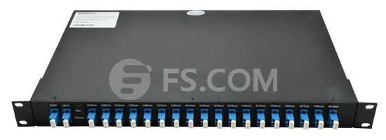
CWDM (coarse wavelength division multiplexing) is an excellent choice for increasing bandwidth capacity while keeping costs down in short-range communication networks. CWDM Mux/Demux modules are bidirectional passive optical multiplexers and demultiplexers, allowing multiple optical signals at different wavelengths to pass through a single optical fiber strand. It can combine up to 18 different wavelength signals from different optical fibers into a single optical fiber, or separates up to 18 different wavelength signals coming from a single optical fiber to 18 separate optical fibers. The following picture shows the front panel of 18 channels 1270-1610nm dual fiber CWDM Mux Demux with monitor port.

18 channels 1270-1610nm dual fiber CWDM Mux Demux
DWDM Mux/Demux
 
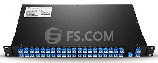
DWDM (dense wavelength division multiplexing) solution is the preferred option for long-haul transmission. The DWDM Mux/Demux modules deliver the benefits of DWDM technology in a fully passive solution. Usually, they are used for long-distance transmission where wavelengths are packed tightly together over the C-band range of wavelengths, up to 48 wavelengths in 100GHz grid (0.8nm) and 96 wavelengths in 50GHz grid (0.4nm). Currently, the most common configuration of DWDM Mux/Demux is from 8 channels to 96 channels. The following picture shows the front panel of 40 channels C21-C60 dual fiber DWDM Mux Demux with monitor port and 1310nm port, which is ideally suited for high-density add/drop requirements in DWDM networks.

40 channels C21-C60 dual fiber DWDM Mux Demux
 
Comparison Between CWDM and DWDM System
 
Price difference—CWDM system carries less data, but the cabling used to run is less expensive and less complex. A DWDM system has much denser cabling and can carry a significantly larger amount of data, but it can be cost prohibitive, especially where there is a need for a large amount of cabling in an application.

Transmission distance—DWDM system is designed for longer distance transmission as stated above. They can transmit more data over a significantly larger run of cable with less interference than a comparable CWDM system. If there is a need for transmitting the data over a long range, DWDM system will likely be the best in terms of functionality of the data transmittal and the lessened interference over the longer distances that the wavelengths must travel.

CWDM system cannot transmit over long distances because the wavelengths are not amplified, and therefore CWDM is limited in its functionality over longer distances. Typically, CWDM can travel anywhere up to about 100 miles (160 km), while an amplified DWDM system can go much further as the signal strength is boosted periodically throughout the run. As a result of the additional cost required to provide signal amplification, the CWDM solution is best for short runs that do not have mission critical data.

FS.COM CWDM & DWDM Mux/Demux Solution
 
Multiplexing enables a high density, scalable fiber solution. It allows an increase in the fiber utilization by carrying multiple signals down an individual fiber connection, rather than investing in more fibers. As a professional manufacturer and supplier in telecommunication industry, FS.COM offers a full range of CWDM & DWDM Mux/Demux. Our Mux/Demux modules are designed for the best possible performance levels, which helps to expand the bandwidth of optical communication networks with lower loss and greater distance capacities. They are protocol transparent and perfectly suit various applications, such as PDH, SDH/SONET, Fibre Channel, etc. With different housing options, the end users can easily add CWDM or DWDM capabilities to their existing or new networks. For more details, please visit www.fs.com.

Originally published: www.fiberopticshare.com/cwdm-dwdm-muxdemux-overview.html


2016年8月3日星期三

40G Transceivers With MTP/MPO Interface vs. 40G Transceivers With LC Interface

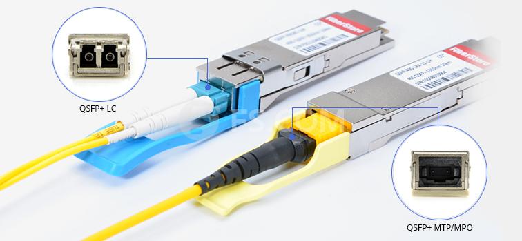
With 40 Gigabit Ethernet commonly deployed in most data centers, it is very essential for the data center managers to employ the suitable 40G devices like 40G QSFP+ transceivers. Nowadays, various 40G transceivers are available on the market, but mainly there are two interfaces adopted by 40G QSFP+ transceivers—MTP/MPO and LC. What’s the difference between these two interface types? This article will have an analysis of the 40G QSFP+ transceivers with MTP/MPO interface and 40G QSFP+ transceivers with LC interface.


40G transceivers


Transmission Distance and Cable Type

Generally, the 40G QSFP+ transceivers with LC interface are used for long distance transmission over single-mode fiber (SMF), and QSFP+ transceivers with MTP/MPO interface are utilized for short distance transmission over multimode fiber (MMF). However, for some 40G transceivers with MTP/MPO interface, such as 40GBASE-PLRL4, and 40GBASE-PLR4, they can support long distance transmission over SMF.

Working Principle

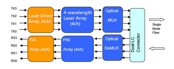
40G QSFP+ transceivers with LC interface—In the transmit side, 4-channel 10G serial data streams are passed to laser drivers. The laser drivers control directly modulated lasers (DML) with wavelengths. Then the output of the four DMLs are optically multiplexed to a SMF through an industry-standard LC connector, combining as 40G optical signal. In the receive side, the 40G optical signals are demultiplexed into 4 individual 10G channels with different wavelength. Each wavelength light is collected by a discrete photo diode, and then outputted as electric data after amplified by a TIA. In this process, a 4-wavelength CWDM multiplexer and demultiplexer is used over a pair of single-mode fibers.

40G QSFP+


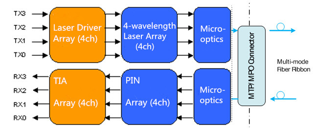
40G QSFP+ transceivers with MTP/MPO interface—In the transmit side, the transmitter converts parallel electrical input signals into parallel optical signals through the use of a laser array. Then the parallel optical signals are transmitted parallelly through the multimode fiber ribbon. In the receive side, the receiver converts parallel optical input signals via a photo detector array into parallel electrical output signals.

QSFP+ transceiver


Note: there are some 40G transceivers with MTP/MPO interface working over SMF as mentioned above. For this kind of PSM (a parallel single-mode optical transceiver with an MTP/MPO fiber ribbon connector) QSFP+, it offers 4 independent transmit and receive channels, each capable of 10G operation for an aggregate data rate of 40G over SMF. That is to say, 8 single-mode fibers are used to achieve parallel transmission.

4x10G Connectivity

For the 40G QSFP+ transceivers with LC interface, they cannot be split into 4x10G as they use 4 wavelengths on a pair of single-mode fibers and do not lend themselves to “splitting” into 4 pairs without substantial complexity to split out the wavelengths. For the 40G QSFP+ transceivers with MTP/MPO interface, they can be used in 4x10G connectivity via an external 12-fiber parallel to 2-fiber duplex breakout cable, which connects the 40G module to four 10G optical interfaces.

FS.COM 40G Transceivers Solution

As a professional manufacturer and supplier in optical communication industry, FS.COM provides a series of 40G transceivers to meet various network demands. The following table lists the generic ones. Besides the generic ones, the 40G transceivers compatible with other brands, such as Cisco, Juniper are also available. Most of them are in stock now and can be shipped the same day after order.

ModelInterface TypeCable TypeMax Cable Distance
40GBASE-CSR4MTP/MPOMMF400 m over OM4 MMF
40GBASE-SR4MTP/MPOMMF150 m over OM4 MMF
40GBASE-PLRL4MTP/MPOSMF1.4 km
40GBASE-PLR4MTP/MPOSMF10 km
40GBASE-LR4LC duplexSMF10 km
40GBASE-LR4LLC duplexSMF2 km
40GBASE-ER4LC duplexSMF40 km
40GBASE-LX4LC duplexMMF/SMFOM3/OM4 MMF: 150 m, SMF: 2 km
40GBASE-SR BiDiLC duplexMMF150m@OM4/100m@OM3/30m@OM2
40GBASE-LR4 CFPSC duplexSMF10 km


Originally published: www.fiberopticshare.com/40g-transceivers-mtpmpo-interface-vs-40g-transceivers-lc-interface.html