2015年12月28日星期一

FTTH Access Network Based on GPON

Growing demand for high speed internet drives the new access technologies which enable experiencing true broadband. This leads telecommunication operators to seriously consider the high volume roll-out of optical fiber based access networks. In order to allow faster connections, the optical fiber gets closer and closer to the subscriber. Then FTTH (Fiber To The Home) appears the most suitable choice for a long term objective because it will be easier to increase the bandwidth in the future if the clients are wholly served by optical fibers. FTTH is a future-proof solution for providing broadband services.

Passive optical network (PON) based FTTH access network is a point-to-multipoint, fiber to the premises network architecture in which unpowered optical splitters are used to enable a single optical fiber to serve multiple premises, typically 32-128. The GPON FTTH access network is highly emphasized in this article.

Components of GPON FTTH Access Network

Taking advantages of WDM (wavelength division multiplexing), PON uses one wavelength for downstream traffic and another for upstream traffic on a single fiber. The OLT (Optical Line Terminal) is the main element of the network. Placed in the Local Exchange, OLT is the engine that drives FTTH system. OLT performs the function of traffic scheduling, buffer control and bandwidth allocation. The optical splitter splits the power of the signal and enables sharing of each fiber by many users. ONT (Optical Network Terminal) is deployed at customer’s premises and connected to the OLT through optical fiber and no active elements are present in the link.

GPON FTTH Access Network Architecture

With a tree topology, GPON is able to maximize the coverage with minimum network splits, thus reducing optical power. A FTTH access network comprises five areas, namely a core network area, a central office area, a feeder area, a distribution area and a user area as shown in the following diagram.
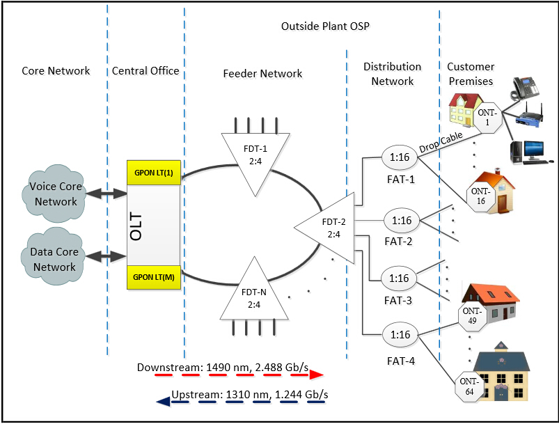
GPON FTTH access network

The core network includes the ISP (internet service provider) equipment, PSTN (packet switched or the legacy circuit switched) and cable TV provider equipment. The main function of the central office is to host the OLT and ODF and provide the necessary powering. The feeder area extends from ODF (optical distribution frames) in the CO (central office) to the distribution points. Distribution cable connects level-1 splitter with level-2 splitter. Level-2 splitter is usually hosted in a pole mounted box placed at the entrance of the neighborhood. In the user area, drop cables are used to connect the level-2 splitter to the subscriber premises.

Traffic Flow in GPON FTTH Access Network

The data is transmitted from OLT to ONT in downstream as a broadcast manner and as a time division multiplexing (TDM) in upstream. The wavelength of the downstream data is 1490 nm. Core network data services transported over the optical network reaches the OLT and then distributed to the ONTs through the FTTH network by dint of power splitting. Every home receives the packets intended to it through its ONT. The upstream represents the data transmission from the ONT to OLT and the wavelength is 1310 nm. If the signals from different ONTs arrive at the splitter input at the same time and at the wavelength 1310 nm, it will lead to superposition of different ONT signals when it reaches OLT. Thus TDMA is adopted to avoid the interference of signals from ONTs. In TDMA time slots will be provided to each user on demand for transmission of their packets. At the optical splitter packets arrive in order and they are combined and transmitted to OLT.

Conclusion

This paper presents the components, architecture, and traffic flow in GPON FTTH access network. The content may not be detailed, but GPON FTTH network architecture is indeed reliable, scalable, and secure. It is a passive network, so there are no active components from the CO to the end user, which dramatically minimizes the network maintenance cost and requirements. It is a future-proof architecture.

Article source: www.fiberopticshare.com/ftth-access-network-based-on-gpon-2.html
2015年12月16日星期三

Introduction to PON Technologies

Passive optical network (PON) is a very significant class of fiber access system in the world and it enjoys a dominant position in the access market. GPON and EPON are the two classifications of PON. The primary differences between the GPON and EPON lie in the protocols used for upstream and downstream communications. This article will introduce PON, GPON and EPON sequentially.

Passive Optical Networks (PON)
 
A PON is a fiber network that only uses fiber and passive components like PON splitters and combiners rather than active components like amplifiers, repeaters, or shaping circuits. Thus PON network costs significantly less than those using active components, but it has a shorter range of coverage limited by signal strength. An active optical network (AON) is able to cover a range to about 100 km (62 miles), while a PON is typically limited to fiber cable runs of up to 20 km (12 miles). PON is also called FTTH (fiber to the home) network.

The typical PON arrangement is a point to multi-point (P2MP) network where a central optical line terminal (OLT) at the service provider’s facility distributes TV or Internet service to as many as 16 to 128 customers per fiber line. Dividing a single optical signal into multiple equal but lower-power signals, the optical splitters distribute the signals to users. An ONU (optical network unit) terminates the PON at the customer’s home. Usually, ONU communicates with ONT (optical network terminal). The ONU/ONT may be one device.

Gigabit Passive Optical Networks (GPON)
 
GPON utilizes optical wavelength division multiplexing (WDM) so a single fiber could be used for both upstream and downstream data. A laser on a wavelength of 1490 nm transmits downstream data, while upstream data transmits on a wavelength of 1310 nm.

While each ONU gets the full downstream rate of 2.488 Gbits/s, GPON uses a time division multiple access (TDMA) format to allocate a specific timeslot to each user. It divides the bandwidth, so each user gets a fraction such as 100 Mbits/s depending on the way the service provider allocates it. The upstream rate is less than the maximum as it is shared with other ONUs in a TDMA scheme. The distance and time delay of each subscriber are determined by the OLT. Then software provides a way to allot timeslots to upstream data for each user. The typical split of a single fiber is 1:32 or 1:64, which means each fiber can serve up to 32 or 64 subscribers. Split ratios up to 1:128 are possible in some systems.

Ethernet Passive Optical Networks (EPON)
 
Based on the Ethernet standard 802.3, EPON 802.3ah specifies a similar passive optical network with a range up to 20 km. EPON uses WDM with the same optical frequencies as GPON and TDMA. The raw line data rate is 1.25 Gbits/s in both the upstream and downstream directions.

EPON technology provides bidirectional 1Gb/s links using 1490nm wavelength for downstream and 1310nm wavelength for upstream, with 1550nm wavelength reserved for future extensions or additional services. EPON is fully compatible with other Ethernet standards, so no encapsulation or conversion is necessary when connecting to Ethernet-based networks on either end. The same Ethernet frame is used with a payload for up to 1518 bytes. As Ethernet is the primary networking technology utilized in local area networks (LAN) and now in metro area networks (MAN), no protocol conversion is needed.

Summary
 
PONs are used to provide triple-play services including TV, and Internet service to subscribers. The lower cost of passive components means simpler systems with fewer components failing or requiring maintenance. The primary disadvantage is shorter range possible, commonly no more than 12 miles or 20 kilometers. As the demand for faster Internet service and more video grows, PONs are growing in popularity. The age of PON has begun. It is a new era of access network upon us.

Article source: www.fiberopticshare.com/introduction-to-pon-technologies.html

2015年12月7日星期一

Things You Should Know about Fiber Optic Connector Polishing

Optical fiber is utilized for high-speed and error-free data transmission across connector assemblies. So the connector end faces need to be polished to optimize performance. And also the connectors must follow acceptance criteria related to insertion and back reflection loss as well as end-face geometry specifications. This article will talk about the fiber optic connectors polishing.

Polishing Process 
 
Early physical contact connectors required spherical forming of their flat end faces as part of the polishing procedure. It involved a four-step process: epoxy removal, ferrule forming, and preliminary and final polishing. These steps utilized aggressive materials for epoxy removal and ferrule forming, generally accomplished with diamond polishing films. Now the polishing process has developed into a sequence of epoxy removal, followed by rough, intermediate and final polishing cycles because almost all connectors are manufactured with a pre-radiused end face. One goal is to avoid excessive disruption of the spherical surface, while still producing a good mating surface.

Polishing Specifications
 
Polishing specifications for fiber connectors fall into two categories related to performance and end-face geometry. Back reflection and insertion loss specifications are the most critical measures of polished end functionality. The insertion loss is the amount of optical power lost at the interface between the connectors caused by fiber misalignment, separation between connections (the air gap) and the finish quality of each connector end. The current standard loss specification is less than 0.5 dB, but less than 0.3 dB is increasingly specified. Back reflection is the light reflected back through the fiber toward the source. High back reflection can translate to signal distortion and, therefore, bit errors in systems with high data transfer rates.

Polishing Material
 
Today several types of connectorized fibers are available, the most common of which are 2.5 mm, 1.25 mm and multifiber. Connector end faces must first be air-polished to ensure a proper mating surface. This will be followed by a sequence of polishing steps depending on the type of connector, the back reflection and the insertion loss specifications. Regardless of the connector type, most polishing sequences begin with aggressive materials, including silicon carbide to remove epoxy and diamond lapping films for beginning and intermediate polishing. These remove both surrounding material and fiber at the same rate. But the last polishing step needs a less aggressive material to attack only the fiber, such as silicon dioxide. Using a material for final polishing that is too aggressive could result in excessive undercut. The wrong final-polish material can cause excessive protrusion, leading to fiber chipping and cracking during the connector mating process.

Impact Factor
 
Issues to be examined include the polishing films used, the type of epoxy and lubrication. Films are the most significant impact because the gradations and quality vary from supplier to supplier. End users should pay attention on selecting film type. Excessively aggressive films can destroy a 125-μm fiber and the end-face radius. Epoxy removal is also essential to contamination-free polishing. Some types of epoxies can be removed more easily with specific grades of silicon-carbide polishing films. The films to use in this step depend on the size of the epoxy bead mounted on the connector end face and the epoxy type. Epoxies have different varieties. Some will be tacky, some firm. In all, a contamination-free environment is essential to optimizing connector polishing.

Polishing may be an old art form, but for the immediate future, it’s here to stay. Undoubtedly inspection criteria will increase. Polishing procedures will be driven to change, and new connector style will also make us continuously strive to reinvent our approach to polishing. Fiberstore has various products about fiber optic polishing. For more details, please visit FS.COM.

Article source: www.fiber-optic-components.com/things-your-should-know-about-fiber-optic-connector-polishing.html

2015年12月1日星期二

Evolution of Flat, PC, UPC and APC Fiber Connectors

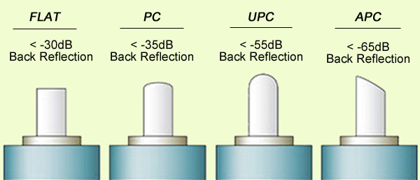
When a connector is installed on the fiber end, loss will be incurred. Some light loss would be reflected back directly down the fiber towards the light source that generated it. These back reflections, or Optical Return Loss (ORL) will damage the laser light sources and also disrupt the transmitted signal. Fiber connectors with different polishing types have different back reflections (see the picture below). With the development of technology, four polishing types are available: flat-surface, Physical Contact (PC), Ultra Physical Contact (UPC), and Angled Physical Contact (APC). How one evolves into another? This article will tell the answer.

polishing type
Flat Fiber Connector
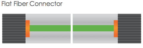
The original fiber connector is a flat-surface connection, or a flat fiber connector. The primary issue of it is that a small air gap between the two ferrules is naturally left when mated. This is partly because the relatively large end-face of the connector allows for numerous slight but significant imperfections to gather on the surface. The flat fiber connector is not suitable for single-mode fiber cables with a 9µm core size, thus it is essential to evolve into Physical Contact (PC) connectors.

flat fiber connector
PC Fiber Connector
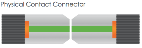
The Physical Contact is polished with a slight spherical design to reduce the overall size of the end-face, which helps to decrease the air gap issue faced by Flat Fiber connectors. It results in lower Optical Return Loss (ORL) with less light being sent back towards the power source.

PC connector
UPC Fiber Connector
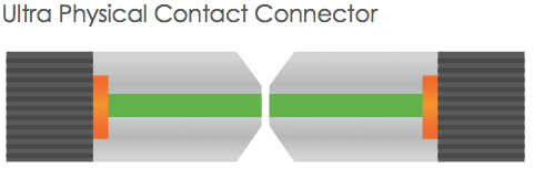
Building on the convex end-face attributes of the PC, but utilizing an extended polishing method creates an even finer fiber surface finish: Ultra Physical Contact (UPC) connector. It has a lower back reflection (ORL) than a standard PC connector and allows more reliable signals in digital TV, telephony and data systems. UPC fiber connector could be used with both single-mode fiber and multimode fiber. Usually the UPC single-mode fiber connector is blue, but the UPC multimode fiber connector is beige. (Note: 10G UPC multimode fiber connector is aqua.)

UPC connector

PC and UPC connectors do have a low insertion loss, but the back reflection (ORL) depends on the the surface finish of the fiber. The finer the fiber grain structure, the lower the back reflection. When PC and UPC connectors are continually mated and unmated, the back reflection will begin to degrade. So there is a need for a connector with low back reflection and it could sustain repeated matings/unmatings without ORL degradation.

APC Fiber Connector
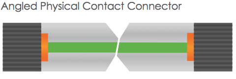
The end faces of Angled Physical Contact connectors are still curved but are angled at an industry standard eight degrees, which allows for even tighter connections and smaller end-face radii. Combined with that, any light that is redirected back towards the source is actually reflected out into the fiber cladding, again by the virtue of the 8°angled end-face. APC connector back reflection does not degrade with repeated matings/unmatings. APC fiber connector can only be used with single-mode fiber and it is green.

APC connector

It is clear that all of the connector end-face options mentioned above take a place in the market. And it is hard to claim that one connector beats the others when your specification needs to consider cost and simplicity not just optical performance. Your particular need decides which one to choose. For those applications calling for high precision optical fiber signaling, APC should be the first consideration, but less sensitive digital systems will perform equally well using UPC. For various connector options, please visit FS.COM.

Article source: www.fiber-optic-components.com/evolution-of-flat-pc-upc-and-apc-fiber-connectors.html