显示标签为“optical splitter”的博文。显示所有博文

2016年11月1日星期二

Understanding the Split Ratios and Splitting Level of Optical Splitters

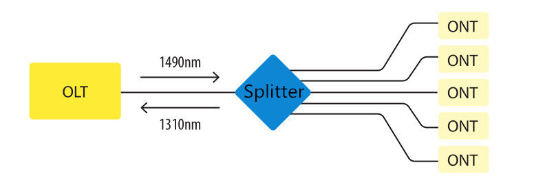
Optical splitters play an important role in FTTH PON networks where a single optical input is split into multiple output, thus allowing a single PON interface to be shared among many subscribers. The optical splitters have no active electronics and don’t require any power to operate. They are typically installed in each optical network between the PON OLT (optical line terminal) and ONTs (optical network terminals) that the OLT serves. Generally, two kinds of fiber optic splitters are popular, which are FBT splitters and PLC splitters. The differences between the two have been stated in another article—FBT Splitters vs. PLC Splitters: What Are the Differences? So it is unnecessary to go into the details here. Besides these, what other information do you know about optical splitters? Keep reading this article, you may get more about 
it.
fiber optic splitter 

Split Ratios
 
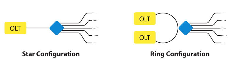
There are a multitude of split ratios available. The most common splitters deployed in a PON system is a uniform power splitter with a 1:N or 2:N splitter ratio, where N is the number of output ports. The optical input power is distributed uniformly across all output ports. Splitters with non-uniform power distribution is also available but such splitters are usually custom made and command a premium. Generally, the 1:N splitters are deployed in star networks, while 2:N splitters are deployed in ring networks to provide physical network redundancy.
1:N splitter and 2:N splitter 

The use of optical splitters in PON allows the service provider to conserve fibers in the backbone, essentially using one fiber to feed as many as 64 end users. A typical split ratio in a PON application is 1:32, meaning one incoming fiber split into 32 outputs. And the qualified fiber optic signal can be transmitted over 20 km. If the distance between the OLT and ONT is small (in 5 km), you can consider about 1:64. With higher split ratios, the PON network has both advantages and disadvantages. Fiber optic splitters with higher split ratios can share the OLT optics and electronics costs as well as share feeder fiber costs and potential new install costs. In addition, larger splits allow more flexibility and fiber management at head end is simpler. At the same time, higher split ratio splitters reduce bandwidth per ONU (optical network unit). And there will be increased optics cost either at OLT or ONU or both to achieve large optical power budgets.

Splitting Level
 
In the PON network, there are two common splitter configurations—centralized approach and cascaded approach.

Centralized Approach
 
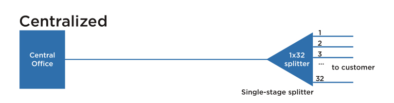
The centralized splitter approach typically uses a 1x32 splitter in an outside plant (OSP) enclosure, such as a fiber distribution terminal. The 1x32 splitter is directly connected via a single fiber to an OLT in the central office. On the other side of the splitter, 32 fibers are routed through distribution panels, splice ports or access point connectors to 32 customers’ homes, where it is connected to an ONT. Thus, the PON network connects one OLT port to 32 ONTs.
centralized splitter 

Cascaded Approach
 
The cascaded approach may use a 1x4 splitter residing in an outside plant enclosure. This is directly connected to an OLT port in the central office. Each of the four fibers leaving this stage 1 splitter is routed to an access terminal that houses a 1x8, stage 2 splitter. In this scenario, there would be a total of 32 fibers (4x8) reaching 32 homes. It is possible to have more than two splitting stages in a cascaded system, and the overall split ratio may vary (1x16=4x4, 1x32=4x8, 1x64=4x4x4).
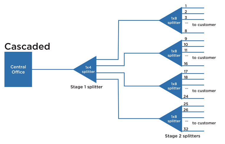
cascaded splitter 

Which to Choose?
 
It is important to understand both architectures in detail and weigh the trade-offs when deciding on the best approach. For most applications, the centralized approach is recommended.

First and foremost, the centralized approach maximizes the highest efficiency of expensive OLT cards. As each home in this approach is fiber-connected directly back to a central hub, there are no unused ports on the OLT card and 100% efficiency is achieved. This also allows a much wider physical distribution of the OLT ports—extremely important when initial “take rates” are projected to be low to moderate. Secondly, centralized approach is able to provide easy testing and troubleshooting access. The centralized 1x32 splitter with distribution ports enables OTDR trace development upstream to the central office and downstream to the access terminal. Also the connector ports available at the distribution hub enable qualification testing of the distribution cabling. Thirdly, loss will occur when splitters are cascaded together. The combined loss effect can reduce the distance a signal can travel, imposing distance limitations on fiber runs. The centralized splitter minimizes that signal loss by eliminating extra splices or connectors from the distribution network.

In general, the centralized architecture typically offers greater flexibility, lower operational costs and easier access for technicians, while the cascaded approach may yield a faster return-on-investment, lower first-in costs and lower fiber costs.

Summary
 
This article has reviewed some information about the split ratios and splitting level of fiber optic splitters. It is very essential to make clear all these different configurations, or the network performance will be influenced if misunderstanding or misusing the optical splitters. Hope the information in this article can help when needed.

2016年9月24日星期六

FBT Splitters vs. PLC Splitters: What Are the Differences?

Fiber optic splitters play an increasingly significant role in many of today’s optical network topologies. They provide capabilities that help users maximize the functionality of optical network circuits from FTTx systems to traditional optical networks. And usually they are placed in the central office or in one of the distribution points (outdoor or indoor). This article will tell something about optical splitters.

What Is Fiber Optic Splitter?
 
A fiber optic splitter is a passive optical device that can split or separate an incident light beam into two or more light beams. These beams may or may not have the same optical power as the original beam, based on the configuration of the splitter. By means of construction, the outputs of a splitter can have varying degrees of throughput, which is highly beneficial when designing optical networks, whether the splitter is used for network monitoring or for a loss budget in a passive optical network (PON) architecture. Generally, there are two types of fiber optic splitters, which are FBT (fused biconical taper) splitters and PLC (planar lightwave circuit) splitters.

fiber opitc splitter
 
FBT Splitters
 
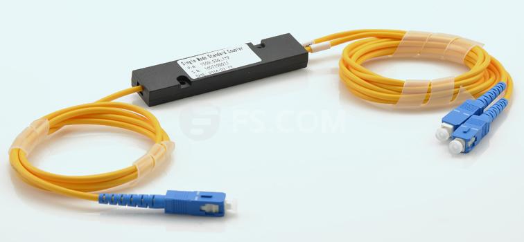
FBT is the traditional technology in which two fibers are placed closely together, typically twisted around each other and fused together by applying heat while the assembly is being elongated and tapered. A signal source controls the desired coupling ratio. The fused fibers are protected by a glass substrate and then protected by a stainless steel tube, typically 3 mm diameter by 54 mm long. FBT splitters are widely accepted and used in passive optical networks. The following picture shows a 1×2 FBT splitter single-mode three window fiber splitter with ABS box.

FBT splitter
 
PLC Splitters
 
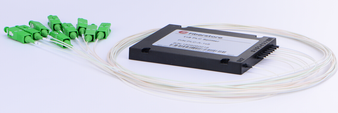
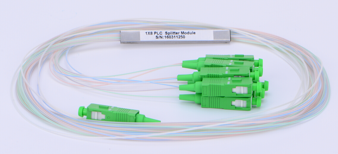
The PLC splitters are used to separate or combine optical signals. A PLC is a micro-optical component based on planar lightwave circuit technology and provides a low cost light distribution solution with small form factor and high reliability. PLCs are manufactured using silica glass waveguide circuits that are aligned with a v-groove fiber array chip that uses ribbon fiber. Once everything is aligned and bonded, it is then packaged inside a miniature housing. PLC splitters have high quality performance, such as low insertion loss, low PDL, high return loss, etc. The following is a picture of 1×8 blockless PLC splitter.

PLC splitter
 
Comparison Between FBT Splitters and PLC Splitters
 
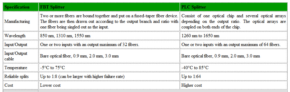
The differences between FBT splitters and PLC splitters are described in the following table.

FBT vs. PLC 

In a word, the FBT splitters have lower costs but restricted to the operating wavelength, and the maximum insertion loss will vary depending on the split and increase substantially for those splits over 1:8. While the PLC splitters, with higher costs, have equal splitter ratios for all branches as well as low failure rate.

FS.COM Fiber Optic Splitters Solution
 
As a leading supplier in fiber optic communication industry, FS.COM provides various kinds of PLC splitters and FBT splitters. Moreover, our fiber optic splitter quality and performance is not only guaranteed by using high-quality components and stringent manufacturing processes and equipment, but also by adherence to a successful quality assurance program, which can be checked in “FS.COM Quality Assurance Program for PLC Splitter”. For more details, you can visit www.fs.com.

2015年12月28日星期一

FTTH Access Network Based on GPON

Growing demand for high speed internet drives the new access technologies which enable experiencing true broadband. This leads telecommunication operators to seriously consider the high volume roll-out of optical fiber based access networks. In order to allow faster connections, the optical fiber gets closer and closer to the subscriber. Then FTTH (Fiber To The Home) appears the most suitable choice for a long term objective because it will be easier to increase the bandwidth in the future if the clients are wholly served by optical fibers. FTTH is a future-proof solution for providing broadband services.

Passive optical network (PON) based FTTH access network is a point-to-multipoint, fiber to the premises network architecture in which unpowered optical splitters are used to enable a single optical fiber to serve multiple premises, typically 32-128. The GPON FTTH access network is highly emphasized in this article.

Components of GPON FTTH Access Network

Taking advantages of WDM (wavelength division multiplexing), PON uses one wavelength for downstream traffic and another for upstream traffic on a single fiber. The OLT (Optical Line Terminal) is the main element of the network. Placed in the Local Exchange, OLT is the engine that drives FTTH system. OLT performs the function of traffic scheduling, buffer control and bandwidth allocation. The optical splitter splits the power of the signal and enables sharing of each fiber by many users. ONT (Optical Network Terminal) is deployed at customer’s premises and connected to the OLT through optical fiber and no active elements are present in the link.

GPON FTTH Access Network Architecture

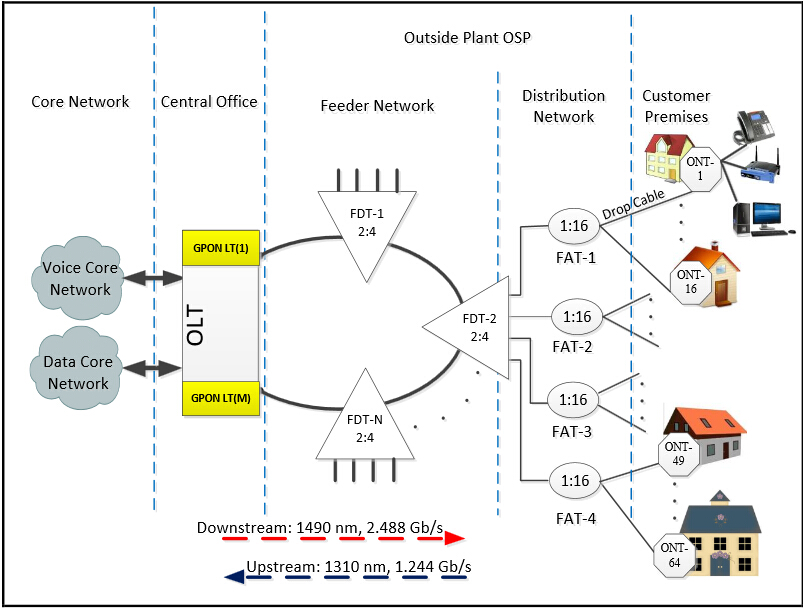
With a tree topology, GPON is able to maximize the coverage with minimum network splits, thus reducing optical power. A FTTH access network comprises five areas, namely a core network area, a central office area, a feeder area, a distribution area and a user area as shown in the following diagram.

GPON FTTH access network

The core network includes the ISP (internet service provider) equipment, PSTN (packet switched or the legacy circuit switched) and cable TV provider equipment. The main function of the central office is to host the OLT and ODF and provide the necessary powering. The feeder area extends from ODF (optical distribution frames) in the CO (central office) to the distribution points. Distribution cable connects level-1 splitter with level-2 splitter. Level-2 splitter is usually hosted in a pole mounted box placed at the entrance of the neighborhood. In the user area, drop cables are used to connect the level-2 splitter to the subscriber premises.

Traffic Flow in GPON FTTH Access Network

The data is transmitted from OLT to ONT in downstream as a broadcast manner and as a time division multiplexing (TDM) in upstream. The wavelength of the downstream data is 1490 nm. Core network data services transported over the optical network reaches the OLT and then distributed to the ONTs through the FTTH network by dint of power splitting. Every home receives the packets intended to it through its ONT. The upstream represents the data transmission from the ONT to OLT and the wavelength is 1310 nm. If the signals from different ONTs arrive at the splitter input at the same time and at the wavelength 1310 nm, it will lead to superposition of different ONT signals when it reaches OLT. Thus TDMA is adopted to avoid the interference of signals from ONTs. In TDMA time slots will be provided to each user on demand for transmission of their packets. At the optical splitter packets arrive in order and they are combined and transmitted to OLT.

Conclusion

This paper presents the components, architecture, and traffic flow in GPON FTTH access network. The content may not be detailed, but GPON FTTH network architecture is indeed reliable, scalable, and secure. It is a passive network, so there are no active components from the CO to the end user, which dramatically minimizes the network maintenance cost and requirements. It is a future-proof architecture.

Article source: www.fiberopticshare.com/ftth-access-network-based-on-gpon-2.html