2016年1月26日星期二

Data Center 40G Migration with OM3 and OM4 Optical Connectivity

Why Migrate to 40G
With the quick development in data center, cabling infrastructures should provide manageability, flexibility and reliability. Deployment of optical connectivity solutions enables for an infrastructure meeting these requirements for current applications and data rates. Scalability is another key factor that needs to consider when choosing the type of optical connectivity. It refers to not only the physical expansion of the data center with respect to additional servers, switches or storage devices, but to the scalability of the infrastructure to support a migration path for increasing data rates. As technology evolves and standards are completed to define data rates such as 40G/100G, Fibre Channel (32G and beyond) and InfiniBand (40G and beyond), the cabling infrastructures installed today need to provide scalability to accommodate the need for more bandwidth in support of future applications. Moreover, current data rates cannot meet the needs of the future with the rising demand to support high-bandwidth applications. 40G technologies and standards, however, can support future networking requirements. Thus, a migration to 40G is required.

40 Gigabit Ethernet Standard
Ratified in June 2010, 802.3ba standard provides a guidance for 40G transmission with multimode and single-mode fibers. And this standard does not have guidance for Cat UTP/STP copper cable. OM3 and OM4 are the only 
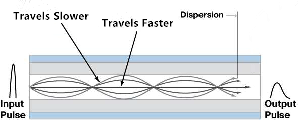
multimode fibers included in the standard. Due to the 850nm VCSEL modulation limits, multimode fibers utilize parallel optics transmission instead of serial transmission. Single-mode fiber guidance utilizes duplex fiber WDM (wavelength-division multiplexing) serial transmission.
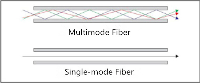
multimode fiber
Compared to single-mode fiber, multimode fiber offers a significant value proposition for short length interconnects in the data center. Unlike traditional serial transmission, parallel optics transmission utilizes an optic module interface where data is simultaneously transmitted and received over multimode fibers. The 40GBASE-SR4 supports 4 x 10G on four fibers per direction.

Cabling Performance Requirements for OM3/OM4

When evaluating the performance needed for the OM3 and OM4 cabling infrastructure, the following criteria should be considered. Each of the criteria would have an impact on the cabling infrastructure’s ability to meet the standard’s transmission distance of 100 meters over OM3 fiber and 150 meters over OM4 fiber.
Bandwidth is the primary criteria. OM3 and OM4 fibers are optimized for 850nm transmission and have a minimum 2000 MHz∙km and 4700 MHz∙km effective modal bandwidth (EMB). Fiber EMB measurement techniques are utilized today. The minimum EMBc (Effective Modal Bandwidth calculate) method combines the properties of both the source and fiber. With a connectivity solution using OM3 and OM4 fibers that have been measured using the minEMBc technique, the optical infrastructure deployed in the data center will meet the performance criteria set forth by IEEE for bandwidth.

Insertion loss is a critical performance parameter in current data center cabling deployments. Total connector loss within a system channel impacts the ability to operate over the maximum supportable distance for a given data rate. The supportable distance at data rate decreases with total connector loss increasing. The 40G standard specifies the OM3 fiber to a 100m distance with a maximum channel loss of 1.9 dB, which includes a 1.5 dB total connector loss budget. OM4 fiber is specified to a 150m distance with a maximum channel loss of 1.5 dB, which includes a 1.0 dB total connector loss budget. The maximum cable fiber attenuation is 3.5 dB/km at 850 nm. So the insertion loss specifications of connectivity components should be evaluated when designing data center cabling infrastructures. With low-loss connectivity components, maximum
flexibility can be achieved with the ability to introduce multiple connector matings into the connectivity link.

Summary

Cabling deployed in the data center today must be selected to provide support of data rate applications of the future. To achieve this purpose, OM3 or OM4 is a must. They provide the highest performance for today’s needs. With 850nm EMB of 2000 MHz∙km and 4700 MHz∙km, the fibers provide the extended reach required for structured cabling installations in the data center. Except the performance requirements, the choice in physical connectivity is also important. Utilizing MTP-based connectivity in today’s installations provides ways to migrate to multifiber parallel optic interface when needed. Therefore, MTP-based connectivity using OM3 and OM4 fiber is the ideal solution in the data center. It can be installed for use in today’s applications, while providing an easy migration path to future higher speed technologies.
 
Article source: www.fiberopticshare.com/data-center-40g-migration-with-om3-and-om4-optical-connectivity.html

2016年1月21日星期四

Factors That Limit Optical Transmission Distance

Nowadays, fiber optic network is gaining its popularity because it has high speed, high density and high bandwidth, etc. Compared with traditional copper cable, the fiber optic cable could support much further distance although the exact distance is limited by many factors. For the super fast optical communication, transmission distance has already become the most vital issue. The optical signal may become weak over long distance. Thus, many components and methods have been adopted to break the limitations of the optical transmission distance. This article will emphasize the factors that limit optical transmission distance.

Optical Fiber Cable Type
Typically, the dispersion in the fiber optic cable could have a great impact on the transmission distance. There are two types of dispersion—chromatic dispersion and modal dispersion. Chromatic dispersion is the spreading of the signal over time resulting from the different speeds of light rays, while modal dispersion is the spreading of the signal over time resulting from the different propagation mode.

As it is known to all, optical fiber cable could be divided into single-mode fiber cable and multimode fiber cable. For the single-mode fibers, transmission distance is affected by chromatic dispersion, because the core of single-mode fibers is much smaller than that of multimode fibers. And this is the main reason why single-mode fiber can have longer transmission distance than multimode fiber. For the multimode fibers, transmission distance is largely affected by the modal dispersion. Due to the fiber imperfections, the optical signals of multimode fibers cannot arrive simultaneously and there is a delay between the fastest and the slowest modes, which causes the dispersion and limits the performance of multimode fibers (see the following picture).
modular dispersion
Light Source of Fiber Optic Transceiver
Fiber optic cable is the path sending the optical signals. However, most of the terminals are electronic based. The conversions between electrical signals and optical signals are necessary. Fiber optic transceivers are widely used in today’s optical network to achieve this purpose. The conversion of signals depends on a LED (light emitting diode) or a laser diode inside the transceiver, which is the light source of fiber optic transceiver. The light source can also affect the transmission distance of a fiber optic link.

LED diode based transceivers can only support short distances and low data rate transmission. Thus, they cannot satisfy the increasing demand for higher data rate and longer transmission distance. For longer and higher transmission data rate, laser diode is used in most of the modern transceivers. The most commonly used laser sources in transceivers are Fabry Perot (FP) laser, Distributed Feedback (DFB) laser and Vertical-Cavity Surface-Emitting (VCSEL) laser. The following chart shows the main characteristics of these light sources.

light source of fiber optic transceiver
Frequency of Transmission
As is shown in the above chart, different laser sources support different frequencies. The maximum distance of fiber optic transmission system can support is affected by the frequency at which the fiber optic signal will be transmitted. Generally the higher the frequency, the longer distance the optical system can support. So it is essential to select the right frequency to transmit optical signals. Typically single-mode fibers use frequencies of 1300 nm and 1550 nm, while multimode fibers use frequencies of 850 nm and 1300 nm.

Bandwidth
Another factor influencing the transmission distance is the bandwidth of fiber optic cables. Generally, the transmission distance decreases proportionally, as the bandwidth increases. For example, a fiber that can support 500 MHz bandwidth at a distance of one kilometer will only be able to support 250 MHz at 2 kilometers and 100 MHz at 5 kilometers. Single-mode fibers have an inherently higher bandwidth than multimode fibers due to the way in which light passes through them.

Splices and Connectors
Splices and connectors in most fiber optic system are inevitable. Signal loss can be caused when the optical signal passes through each splice and connector. The total amount of the loss depends on the types, quality and number of connectors and splices.

Conclusion
According to the above statement, the optical transmission distance is affected by various factors including the fiber type, light source of transceiver, frequency of transmission, bandwidth as well as splices and connectors. So it is necessary to consider these factors to minimum the limitations on transmission distance when deploying the fiber optic network.

Article source: www.roarsummit.com/factors-that-limit-optical-transmission-distance-1562133546.html

2016年1月16日星期六

How to Make, Lay and Repair Submarine Cables?

Ninety-nine percent of international data is transmitted by submarine communication cables laid on the sea bed between land-based stations to carry telecommunication signals across stretches of ocean. These undersea cables are hundreds of thousands of miles long and can be as deep as Everest Is tall, as well as enable our globalized society by facilitating the transfer of digital information. This article will tell how to make, lay and repair submarine cables.

How to Make Submarine Cables?
The core of undersea cables is covered with brass tape which is impervious to the assault of the aqueous worm called teredo which is the greatest enemies of submarine cables. The completed core with the brass taping is fully wrapped by jute yarn, a coarse hemp, steeped in a tarry preservative. Wound around the core, this jute yarn serves as a bedding for the outer protecting wires. After several servings of the jute yarn have been applied to the core, the whole is then covered with galvanized iron wires which vary in number and thickness according to the depth of water the cables is to lay in.

Cables laid in deep water are lighter than those laid in shoaler water. Why? Because if the cables are too heavy in deep water, the strain of raising cables would be so great that it may be impossible to recover the cables for repair purposes. Moreover, there is very little to injure submarine cables in the deep water.

How to Lay Submarine Cables?
The laying of long submarine cables is not easy. The telecom engineers toil long and tedious hours to make this possible. Submarine cables are laid down by using specially modified ships. On reaching the place selected for the landing of the cable, the ship approaches as close to the shore as possible and, letting go anchor, prepares to land the shore end. Some companies use rafts to achieve this, while others use a couple of spider-sheaves, or large VV-shaped wheels in light iron frames are sent ashore and fixed by sand anchors some 60 yards apart. Hauling lines are paid out from the ship, reeved through the sheaves and brought back on board again. One end of this continuous lines is attached to the picking-up gear and the other to the cable. The engines are then set in motion, and the cable is dragged slowly out of the ship towards the shore. As it goes, large wooden casks or inflated India rubber buoys are lashed to it every 50 or 60 feet, to keep it afloat and prevent the damage which would result from it being dragged along the bottom.

submarine cable

When sufficient cable has been landed, the length on shore is laid in a trench which runs from low water mark to the cable landing station (CLS), and the end is inserted through a hole in the floor. Then there will be testing and speaking instruments set up in the CLS. For day and night, the testing goes on. The ship gets slowly under way when a satisfactory test has been taken.

How to Repair Submarine Cables?
The first indication that a cable is broken or faulty is the failure of the receiving apparatus to properly record incoming signals. When a break or a fault in the line is indicated by the receiving instruments, a test is immediately made from each end of the line. These tests are taken with very sensitive apparatus. Several methods of testing are employed in the localization of complete or partial interruptions of cables, with the most general being the Wheatstone Bridge balance.

The operation of repairing submarine cables is no child’s play. It is a kind of work which requires sturdy and fearless manhood as well as skillful seamanship. Most of the breaks happen during seasons of the year when the weather conditions at sea are most severe. It is common for a cable ship to spend months at sea waiting for suitable weather conditions to carry on operations.

Conclusion
By reading the above statements, have you got more knowledge about the submarine cables’ making, laying and repairing? It may not be rich in content, but submarine cables are indeed important members of fiber cables and do play an important role in international data transmission.

2016年1月11日星期一

Splice or Connector: Which to Choose for FTTH Drop Cable Installation?

When deploying a FTTH network, subscribers must choose the right drop cable interconnect solution. So they need to decide whether to use splices (permanent joint) or connectors (easily mated and unmated by hand) for the best solution. This is for both ends of the drop cable—the distribution point and at the home’s optical network terminal (ONT) or network interface device (NID). Splices and connectors are widely used at the distribution point, while at the ONT/NID, a field-terminated connector or a spliced-on factory-terminated connector is used. This paper discusses the available interconnect solutions (splices and connectors) for FTTH drop cables and their own pros and cons.


Splices: Pros and Cons
Excellent optical performance is the most significant advantage of splices. And splicing can also eliminate the possibility of the interconnection point becoming dirty or damaged, potentially compromising signal integrity, as may happen to a connector end face when it is being handled while unmated. Contaminants will cause high optical loss or even permanently damage the connector end face. Splice enables a transition from 250µm drop cable to jacketed cable.

The major drawback of splice is its lack of operational flexibility. To reconfigure a drop at the distribution point (in the case of one subscriber dropping FTTH service and another one adding it) one splice must be removed, fibers rearranged, and two new fibers spliced. Then it requires the technician to carry special splicing tools for simple subscriber changes. Moreover, other customers’ service may be disrupted by the fiber-handling process. 250µm fiber cable is usually used at the distribution point, which is easily bent and then cause high optical loss or even break the fiber. If a splice is used at the ONT, a tray is needed to hold and protect the splice, which increase the ONT size and potentially the cost.

According to above description, splice is appropriate for drops where there is no need for future fiber rearrangement, typically in a greenfield or new construction application where all of the drop cables could be easily installed during the living unit construction.


Connectors: Pros and Cons
Due to the characteristic of being mated and unmated repeatedly, connectors can provide greater network flexibility. Without any tools, a technician can easily connect or disconnect subscribers. Connector could also provide an access point for networking testing.

Material cost is the connector’s most obvious downside. They cost more than splices, although network rearrangement is much cheaper. So providers need weight the connector’s material cost and its potential for contamination and damage against the greater flexibility and lower network management expense.

Connectors could be used to connect different subscribers as needed for distribution points. It must be installed at the ONT and then offers flexibility both at the curb and at the home.


Choose the Right Splice
Once the decision goes to splices, the type of splicing (fusion and mechanical) must be determined.

Fusion splicing has been the de facto standard for fiber feeder and distribution construction networks. Fusion splicer is used for FTTH drop splicing as it provides a high quality splice with low insertion loss and reflection (see the picture below). However, the initial capital expenditures, maintenance costs and slow installation speed of fusion splicing hinder its status as the preferred solution. Fusion splicing is best suited for companies which have invested in fusion splicing equipment and have no need to purchase additional splicing machines.

FS2808 Digital Fiber Fusion Splicer

Mechanical splices are successfully deployed around the world in FTTH installation, but not popular in United States because the index matching gel inside the splices can yellow or dry out, resulting in service failures. Great strides have been made in improving gel performance and longevity over the last 20 years.


Choose the Right Connector
Once choosing to use a connector, a factory-terminated or field-terminated connector must be decided.

Factory-terminated drop cables provides high-performing and reliable connections with low optical loss. By reducing installation time, factory termination keeps labor costs low. However, factory-terminated cables are expensive compared to field-terminated alternatives. And they require a cable management system to store slack cable at the curb or in home.

The installation of field-terminated connectors can be customized by using a reel of cable and connectors. Fuse-on connectors use the same technology as fusion splicing to provide the highest level of optical performance in a field-terminated connector. Mechanical connectors provide alternatives to fuse-on connectors for field installation of drop cables.

Depending upon service provider requirements and living unit configurations, a hybrid solution of a field-terminated connector on one end of the drop cable and a factory-terminated connector on the other may be the optimal solution.


Summary
The drop cable interconnect solution is a key component of a FTTH network. Selecting the right connectivity product not only offers cost savings and efficient deployment but also provides reliable service to customers. Most FTTH drop cable installations have been field terminated on both ends of the cable with mechanical connectivity solutions.

2016年1月4日星期一

How Much Do You Know About FTTH PON Testing?

Passive optical network (PON) is a cost-effective way to deliver high-bandwidth broadband services to users and widely deployed all over the world. FTTH uses PON technology and provides high bandwidth from the central office (CO) to subscribers. FTTH PON system achieves network reliability and makes network testing, monitoring and measuring easier. This article will tell about FTTH PON testing from the four aspects below.

Connector Inspection

Connector inspection/cleaning plays an important role in network installation and maintenance. Typically an optical microscope is used for connector inspection. To prevent accidental eye damage when inspecting fibers potentially carrying live traffic, a video microscope images the connector end-face and displays the magnified image on a handheld display. In this way, the dirt, debris or damage on the connector could be easily detected. According to the study by NTT-Advanced Technology, connector contamination and damage are the key reason for poor optical network performance.

Insertion Loss Test

In telecommunications, the term “insertion loss” expressed in dB, refers to the loss of signal power resulting from the insertion of a device in a transmission line or in an optical fiber. An insertion loss test measures the end-to-end loss of the installed link by injecting light with a known power level and wavelength at one end, and then measures the received power level output from the other end. The measured difference between the transmitted and received power levels exactly indicates the very optical loss through the network. In some occasions, insertion loss is allowed and considered acceptable when the measured loss level is lower than the budget loss level.

Optical Return Loss Test

In telecommunications, return loss expressed in dB, means the loss of power in the signal returned or reflected by a discontinuity in a transmission line which can be a mismatch with the terminating load or with a device inserted in the line. The optical return loss test injects light with known wavelength and power level into one end and measures the power level returned to that same end. Then the return loss is the difference between the injected power level and the measured return level. When the return loss is higher than the budgeted return loss target, it is considered acceptable.

Typically insertion loss test and return loss test are performed by using wavelengths at those which will be used during network operation. For FTTH PON system, 1310nm wavelength is used in the upstream direction, while 1490nm and 1550nm wavelengths are used in the downstream direction. So it is essential to have insertion and return loss testing at 1310nm, 1490nm and 1550nm wavelengths. The optical network is considered ready for activation when the insertion loss and return loss measured at each wavelength are within the budgeted levels for the link. However, in some cases, the network operator uses an optical time domain reflectometry (OTDR) as the following picture shows for more fully documented network.

JDSU MTS 4000 OTDR


Optical Time Domain Reflectometry (OTDR)

OTDR scans a fiber from one end to measure the length, loss and optical return loss of an optical network. And it also locates and measures reflective or non-reflective events in the network caused by splices, connectors, splitters, faults, etc. OTDR operates like a radar by injecting narrow pulses of light into the fiber under test. As each pulse travels down the fiber, imperfections in the fiber scatter some of the light, with some of this Rayleigh-scattered light being guided back up the fiber.

Summary

From the above description, four tests are commonly used to verify optical links. Proper testing is critical for FTTH PON installing, activating and maintaining, because excess loss or reflectance can result in poor network performance if not detected and corrected. And over time, transmission errors will occur before the need for any maintenance activity.

Article source: www.fiberopticshare.com/how-much-do-you-know-about-ftth-pon-testing.html