As
is know to all, 40G QSFP+ transceiver modules are hot-swappable,
parallel fiber-optical modules with four independent transmit and
receive channels. These channels can terminate in another 40G QSFP+
transceiver, or the channels can be broken out to four separate 10G SFP+
transceivers. QSFP+ transceiver modules connect the electrical
circuitry of the system with either a copper or an optical external
network. And the transceiver, such as QSFP-40G-SR4,
is used in short reach applications like switches, routers and data
center equipment where it can provide higher density than SFP+ modules.
This article will provide the instructions for the 40G QSFP+ transceiver
installation and removing.
Required Tools
Three
tools are needed to install the 40G QSFP+ transceiver modules. The
first one is a wrist strap or other personal grounding device to prevent
ESD (electro-static discharge) occurrences. The second one is an
antistatic mat or antistatic foam to set the transceiver on. The last
one is fiber-optic end-face cleaning tools and inspection equipment.
Installing 40G QSFP+ Transceivers Modules
QSFP+
transceivers have either a bail-clasp latch or a pull-tab latch.
Installation procedures for both types of latches are provided.
Note:
The QSFP+ transceiver module is a static-sensitive device. Always use
an ESD wrist strap or similar individual grounding device when handling
QSFP+ transceiver modules or coming into contact with system modules.
Follow the steps below to install a QSFP+ transceiver.
Step 1: Attach an ESD wrist strap to yourself and a properly grounded point on the chassis or the rack.
Step 2: Remove the QSFP+ transceiver module from its protective packaging.
Step 3: Check the label on the QSFP+ transceiver module body to verify that you have the correct model for your network.
Step 4: For optical QSFP+ transceivers, remove the optical bore dust plug and set it aside.
Step 5:
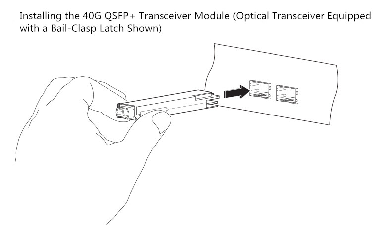
For transceivers equipped with a bail-clasp latch, first keep the
bail-clasp aligned in a vertical position. Second align the QSFP+
transceiver in front of the module’s transceiver socket opening and
carefully slide the QSFP+ transceiver into the socket until the
transceiver makes contact with the socket electrical connector.
Step 6:
For QSFP+ transceivers equipped with a pull-tab latch, first hold the
transceiver so that the identifier label is on the top. Second align the
QSFP+ transceiver in front of the module’s transceiver socket opening
and carefully slide the QSFP+ transceiver into the socket until the
transceiver makes contact with the socket electrical connector.
Step 7:
Press firmly on the front of the QSFP+ transceiver with your thumb to
fully seat the transceiver in the module’s transceiver socket.
Step 8:
For optical QSFP+ modules, reinstall the dust plug into the QSFP+
transceivers optical bore until you are ready to attach the network
interface cable. Do not remove the dust plug until you are ready to
attach the network interface cable.
Attaching the Optical Network Cable
Note: Before removing the dust plugs and making any optical connections, please remember the following guidelines.
Firstly,
keep the protective dust plugs installed in the unplugged fiber-optic
cable connectors and in the transceiver optical bores until you are
ready to make a connection. Secondly, inspect and clean the MPO
connector or the duplex LC connector end faces before making any
connections. Thirdly, grasp the MPO or the duplex LC connector only by
the connector housing to plug or unplug a fiber-optic cable.
Follow the steps below to attach the optical cables.
Step 1: Remove the dust plugs from the optical network interface cable MPO connectors. Save the dust plugs for future use.
Step 2: Inspect and clean the MPO or duplex LC connector’s fiber-optic end faces.
Step 3: Remove the dust plugs from the QSFP+ transceiver module optical bores.
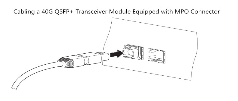
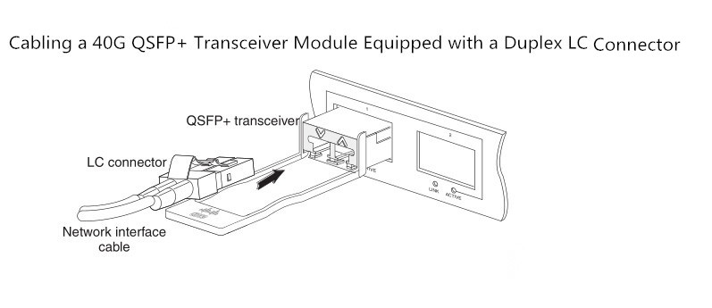
Step 4: Immediately attach the network interface cable MPO connector or duplex LC connector to the QSFP+ transceiver module.
Step 5:
Verify that the optical network cable is fully seated by pulling gently
on the cable’s MPO or duplex LC connector boot. If the network cable
disconnects, reinstall it and make sure that the cable connector is
fully seated and that the connector latch engages.
Removing 40G QSFP+ Transceiver Modules
Follow the steps below to remove a QSFP+ transceiver.
Step 1: For optical QSFP+ transceivers, disconnect the network interface cable from the QSFP+ transceiver connector.
Step 2:
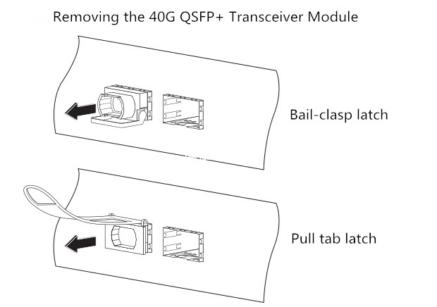
For QSFP+ transceivers equipped with a bail-clasp latch, first pivot
the bail-clasp down to the horizontal position. Second immediately
install the dust plug into the transceivers optical bore. Third grasp
the sides of the QSFP+ transceiver and slide it out of the module
socket.
Step 3:
For QSFP+ transceivers equipped with a pull tab latch, first install
the dust plug into the transceiver’s optical bore immediately. Second
grasp the tab and gently pull to release the transceiver from the
socket. Third slide the transceiver out of the socket.
Step 4: Place the QSFP+ transceiver into an antistatic bag.
Conclusion
The above statements illustrate how to install a 40G QSFP+ transceiver,
attach an optical network cable and remove a QSFP+ transceiver module.
It is necessary to know the correct way of installing and removing a
QSFP+ transceiver as correct operation can protect the 40G transceiver
from being damaged and ensure its stable performance.


