Ethernet
technology has continually evolved in order to meet the never-ending
requirement for faster rates of data transmission. The demand for faster
application speeds has also spurred technological evolution on data
carrying techniques. As such, copper and fiber transmission standards
have progressed, providing greater bandwidth for transporting data over
Ethernet architectures with reduced cost and complexity. This article
highlights the cabling solutions for 1 Gigabit Ethernet and 10 Gigabit
Ethernet.
1 Gigabit Ethernet Cabling
For 1 Gigabit Ethernet cabling, both fiber and copper cable connections are available.
Fiber Cabling
The
optical fiber cables are usually used for longer connections. Optical
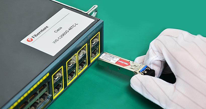
fiber connections are constructed with a combination of a transceiver,
which receives digital signals from the Ethernet device (switch or
adapter card) and converts them to optical signals for transmission over
the fiber. The most widely used transceiver for 1 Gigabit Ethernet is
SFP (small form factor pluggable). For instance, the Cisco GLC-LH-SMD
1000BASE-LX/LH SFP can support transmission distance up to 10
kilometers.
The
difference in cable choices comes from the distance limitations
encountered with the various types of optical transmission. Short range
and long range are the two different commonly available types. Short
range supports connections of up to 550 meters, while long range
supports connections of up to 10 kilometers. Multimode fiber cables are
typically used for short range transmission and single-mode fiber cables
are used for long range transmission.
The
final consideration on the fiber cable is the connector type. The main
differences among types of connectors lie in dimensions and methods of
mechanical coupling. Multimode fiber cables and single-mode fiber cables
require different connectors. SC and LC connectors are the most common
types.
Copper Cabling
For
copper cables supporting 1 Gigabit Ethernet, the Category 5 unshielded
twisted pair (Cat5-UTP) is utilized. With a RJ45 connector on either
end, Cat 5 can support connections of up to 100 meters. Cat5e, an
enhanced version of the Category 5, is the most used Ethernet cabling
today. For lower speed (10 or 100 Mbps) connections, only two of the
four pairs in Cat 5 cables are used. For 1 Gigabit Ethernet, all four
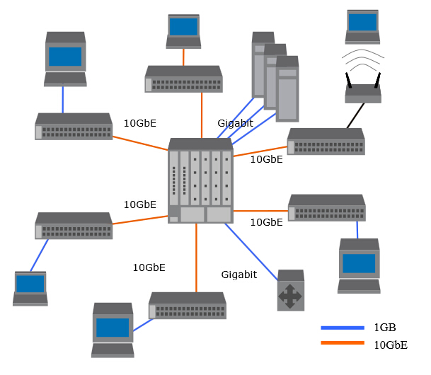
pairs are used. The following picture shows the 1G and 10G application
in an enterprise data center.
10 Gigabit Ethernet Cabling
For
10 Gigabit Ethernet cabling, the cabling choices are nearly the same
with the 1 Gigabit Ethernet. The fiber options are very similar. The
transceivers are somewhat different.
Fiber Cabling
An
enhanced version of the SFP transceivers was standardized for use with
10 Gigabit Ethernet and named SFP+ (enhanced small form factor
pluggable). SFP+ has the same mechanical characteristics as the SFP
transceiver. It is capable of supporting the higher speed—10 Gbps.
Besides SFP+ transceiver, XFP (10 Gigabit small form factor pluggable)
transceiver also can support 10 Gigabit Ethernet. Compared with XFP, the
SFP+ has smaller form factor allowing for much more dense packaging of
ports on switches. Moreover, the direct attach copper cable, supporting
10Gbps Ethernet data transmission, has two SFP+ connectors on both end.
This 10G direct attach copper cable like Cisco SFP-H10GB-CU5M
supports transmission distance up to 12-15 meters, which is often more
than enough for interconnecting systems in racks in data centers. With
these two capabilities, SFP+ has become the predominant 10 Gigabit
Ethernet connector type.
For
10 Gigabit Ethernet fiber connections, the same optical fiber as 1
Gigabit Ethernet is used. The short range fiber cables can support
connections of up to 300 meters and long range fiber cables can support
connections of up to 2 kilometers. Besides these two, a new option is
also available—extended range (for connections of up to 10 kilometers).
LC
and SC are also the common connector types. Note that these cables can
be connected to either XFP or SFP+ transceivers. The connector type
defines the mechanical specifications of the fiber-to-transceiver
interface. Thus, one could have a XFP transceiver on one end of a 10G
Ethernet fiber cable and a SFP+ transceiver on the other end. As long as
the cable type and connector type match, there is no problem.
Copper Cabling
For
10 Gigabit Ethernet cabling, the standards body determined that even
the enhanced Cat5e UTP traditional Ethernet cable would not be able to
carry the signal reliably for any significant distance. So a new
specification, still using RJ45 connectors, was introduced and named
10GBASE-T. This calls for a 4-wire twisted pair cable with even more
stringent limitations on cross-talk. It is called Cat 6a. 10GBASE-T
cables for up to 100 meters are supported.
Summary
For
1 Gigabit Ethernet connection, SFP transceiver, fiber optic cables and
copper cables are the choices. For 10 Gigabit Ethernet connection, 10G
SFP+, 10G XFP, optical fiber cables as well as copper cables are able to
meet the requirements. Fiberstore, a professional company in the field
of optical network devices and interconnection, supplies various fiber
optic transceivers, fiber optic cables and copper cables. Lots of the
fiber optic products, such as SFP-10G-ER SFP+, have large inventory and low price. For more detailed information about us, please visit www.fs.com.
Article source: www.fiberopticshare.com