2017年5月16日星期二

MTP/MPO Connector Cleaning: One-Click Cleaner vs. Cassette Cleaner

With data centers moving to 40G/100G, MPO fiber cables are extensively deployed. To ensure the reliable and efficient performance of the MPO cables, it is critical to clean the MPO connectors before mating to other equipment as contaminated connectors would lead to degraded performance and costly but preventable failures. There are two ways to clean MTP/MPO connectors. One is to use cassette cleaner, while the other is to use one-click cleaner. This post will talk about these two types of cleaning methods for MTP/MPO connectors.

One-Click Cleaner vs. Cassette Cleaner: Using Rules

The one-click cleaner for MTP/MPO connectors is a cost-effective tool for cleaning fiber end-faces without the use of alcohol. It can clean both exposed jumper ends and connectors in adapters with one-push action. A cassette cleaner contains a refillable lint free reel of cloth that is moved after each cleaning, always presenting a clean surface. It is applicable primarily for cleaning connectors with one-wipe action in dry cleaning without any alcohol and other harsh chemicals.

One-Click Cleaner vs. Cassette Cleaner: Cleaning Procedures

For both the two cleaning methods, please always inspect before cleaning. If the connector is already clean, there is no need to clean it.

Cleaning Procedures of One-Click Cleaner (For Connectors in Adapters)
  • Pull off the guide cap.
  • Insert the cleaning tool into the bulkhead and turn the cleaning wheel backwards until click two times.
Cleaning Procedures of One-Click Cleaner (For Exposed Connectors)
  • Carefully pull out the guide cap cover.
  • Insert the patch cord into the cleaning tool, apply slight pressure and turn the cleaning wheel backward until click two times.
one-click cleaner for MTP/MPO connectors
Cleaning Procedures of Cassette Cleaner
  • Remove connector dust cover.
  • Select the appropriate cleaner for male/female.
  • For female MTP/MPO connectors, use the cleaning brush and fluid to remove any debris from the pin holes.
  • Depress the lever so that a fresh area of cleaning cloth is exposed.
  • Position the ferrule against the cloth so that the fibers are in contact with the cleaning material. In the case of angled connectors, the ferrule will need to be adjusted accordingly.
  • Wipe the connector in the direction shown on the cassette.
  • Release the grip to seal off the cleaning cloth.
  • Let the ferrule air-dry before inspecting with a 200xmicroscope.
  • If still contaminated repeat all steps once again.
  • Ensure that the connector does not touch any hard surfaces.
use cassette cleaner to clean MTP/MPO connectors

Note: Do not move connector back and forth. Connector is to be moved in only the direction of the arrows on the cleaner.

One-Click Cleaner vs. Cassette Cleaner: Which to Choose?

From what have described above, we can summarize that one-click cleaner can be used for connectors in adapters and exposed connectors, while cassette cleaner is only applicable for exposed connectors. Moreover, the one-click cleaner is capable of cleaning ferrules with or without guide pins. But for cassette cleaner, you should choose the correct type to clean male or female connectors. In my opinion, one-click cleaner is more convenient. Among the two, which is your choice?

2017年5月10日星期三

Roles of MTP Trunk, MTP Harness, MTP Conversion Harness in 40G/100G Migration

With bandwidth demands continuing to grow, higher and higher capacity and throughput are required in the data center. And to address these needs efficiently and effectively, a strategic approach focusing on existing user expectations and future capacity requirements is wanted. MTP/MPO cable is the good choice that can meet various network requirements. This post will list the roles of different MTP/MPO cables (MTP trunk, MTP harness, MTP conversion harness) in 10G/40G/100G migration.

10G/40G/100G Migration Solutions
 
For upgrading connection data rates, several common scenarios are available with using MTP/MPO fiber cables. Following part will list these applications out for your reference.

10G to 40G: 8-Fiber MTP Harness Cable
 
One commonly used upgrade possibility beyond 10G incorporates four 10G SFP+ transceiver connections to a 40G QSFP+, which requires a 8-fiber MPO-LC harness cable. Figure 1 illustrates one side of the transmission path utilizing this MPO harness cable in conjunction with a 40G QSFP+ to aggregate four 10G SFP+ transceivers. QSFP+ transceivers on the switches yield higher port densities and throughput.

8-fiber MTP LC harness cable in 10G to 40G migration

Figure 1: 10G to 40G upgrade by using MTP/MPO LC harness cable
 
40G to 40G: 12-Fiber MTP Trunk Cable
 
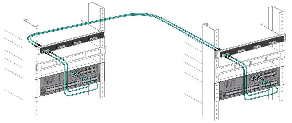
MTP trunk cable incorporates interconnected banks of QSFP+ transceivers (MPO to MPO connectivity). Figure 2 illustrates the connectivity. In this connection, 12-fiber MPO trunk cables are needed to connect the transceivers. Four fibers transmit light, four receive and four unused.

12f MTP trunk cable used in 40G connection 

Figure 2: 40G to 40G connection by using MTP/MPO trunk cable with four fibers unused

40G to 40G: 2x3 MTP Conversion Harness/Module
 
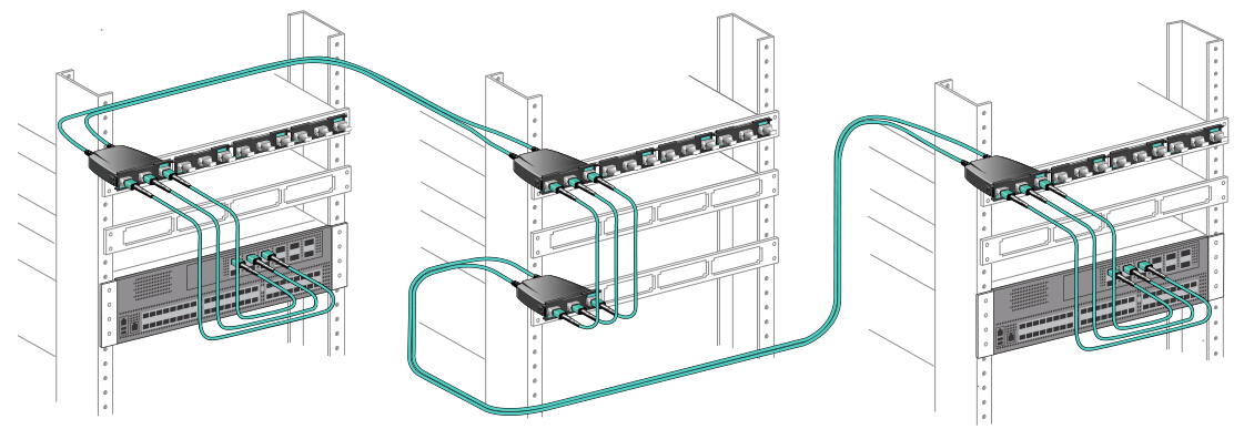
MTP conversion harness and MTP conversion module both take advantage of 100% fiber utilization. For those needing 100% fiber utilization, 2x3 MTP conversion harness or conversion module can achieve the purpose. Connectivity of the 2x3 MTP conversion harness and conversion module is the same. They are interchangeable, but must be used in pairs: one (MTP conversion harness or module) at each end of the link. Figure 3 shows an example of how MTP conversion module uses all fibers to achieve 100% fiber utilization. The eight live fibers from each of the three QSFP+ transceivers are transmitted through the trunks using the full 24 fibers. The second 2x3 conversion module unpacks these fibers to connect to the 3 QSFP+ transceivers on the other end.

MTP conversion cable/module used in 40G with 100% fiber utilization 

Figure 3: 40G to 40G connection with MTP conversion module ensuring 100% fiber utilization

100G to 100G: MTP Trunk Cable
 
For 100G to 100G connection, 24-fiber MTP trunk cable allows direct attach capability of 100GBASE-SR10 CXP or CFP equipped devices, while 12-fiber MTP trunk cable can be used to allow the direct connection for 100G QSFP28 (MPO to MPO) connection.

24f MTP trunk cable in 100G connection 

Figure 4: MTP trunk cable for 100G to 100G connection

10G to 100G/120G: 24-Fiber MTP Harness Cable
 
To achieve 10G to 100G/120G connection, one popular implementation is to use the high density 100G/120G CXP for space-saving. This deployment can leverage the 10G-per-lane channels to distribute the 10G data anywhere in the data center. Figure 5 uses a 24-fiber MTP harness cable that separates each TX and RX pair, allowing connectivity to any duplex path reachable by a patch panel. Simply connect this cable to a 120G CXP transceiver and the customer can access the 12 individual transceiver pairs. When used with a patch panel, this method offers the ultimate in flexibility, allowing connectivity to any row, rack, or shelf.

24 fiber MTP LC harness cable in 10G to 100G connection 

Figure 5: 10G to 100G connection by using 24-fiber MTP LC harness cable

40G to 120G: 1x3 MTP Conversion Harness
 
One way to break out a 120G CXP is to use 1x3 MTP conversion harness cable. Figure 6 shows a 24-fiber fanout that utilizes 24 fibers to split the 12 transceivers into three groups of eight. These eight-fiber groups match the TX/RX fibers used on a QSFP+ transceiver for direct connection to three separate QSFP+ transceivers. Like the 12x10G segregation mentioned above, once split, the 3x8-fiber QSFP+ channels can be distributed through patch panels and 12-fiber based trunking to any area of the data center.

1x3 MTP conversion harness used in 40G to 120G connection 

Figure 6: 40G to 120G connection by using 1x3 MTP conversion harness

Summary
 
Several solution scenarios have been illustrated in this post. From 10G to 40G/100G/120G, we can see that different MTP/MPO fiber cables are used for data transmission. Generally, MTP/MPO trunk cables are used for direct connection between two switches. MTP harness cables are used for data migration to higher data rates. And MTP/MPO conversion cables are used to achieve 100% fiber utilization between two switches. All of those different MTP/MPO fiber cables (MTP trunk, MTP harness, MTP conversion harness) can be found in FS.COM. For more details, please visit www.fs.com.

 
Other post you may be interested: No Conversion vs. Conversion Module vs. Conversion Harness: Which to Use for 40G Parallel Solution?

2017年5月3日星期三

Understanding MTP/MPO Polarity Methods for Parallel Signals

When migrating from 10G to 40G/100G, it is important to know the MTP polarity and gender. Understanding the MTP polarity can ensure that connections between a transmitter and its receiver across the entire fiber optic system are in a consistent, standards-based manner. In the previous post “Introduction to Polarity Methods for MTP/MPO Systems”, I have introduced the polarity systems for duplex signals. So in this article, I would like to talk about MTP/MPO polarity methods for parallel signals.

MTP/MPO Polarity Methods for Parallel Signals
 
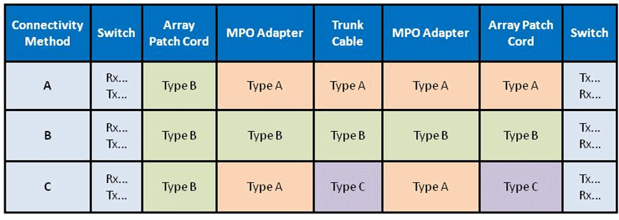
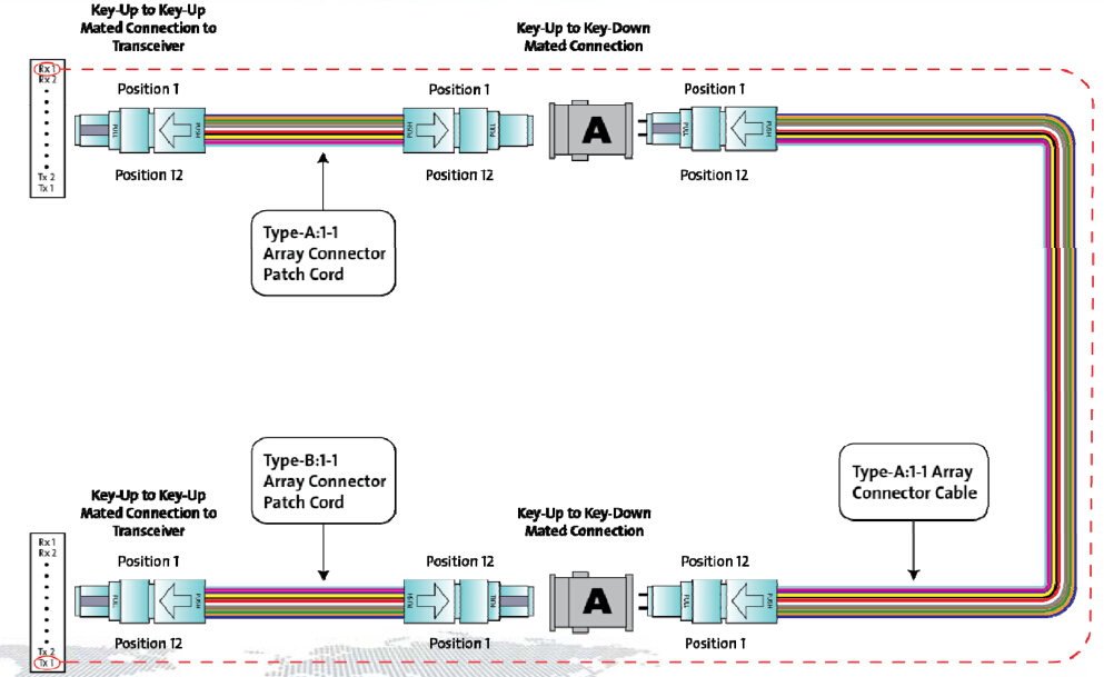
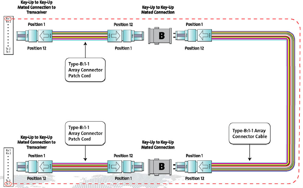
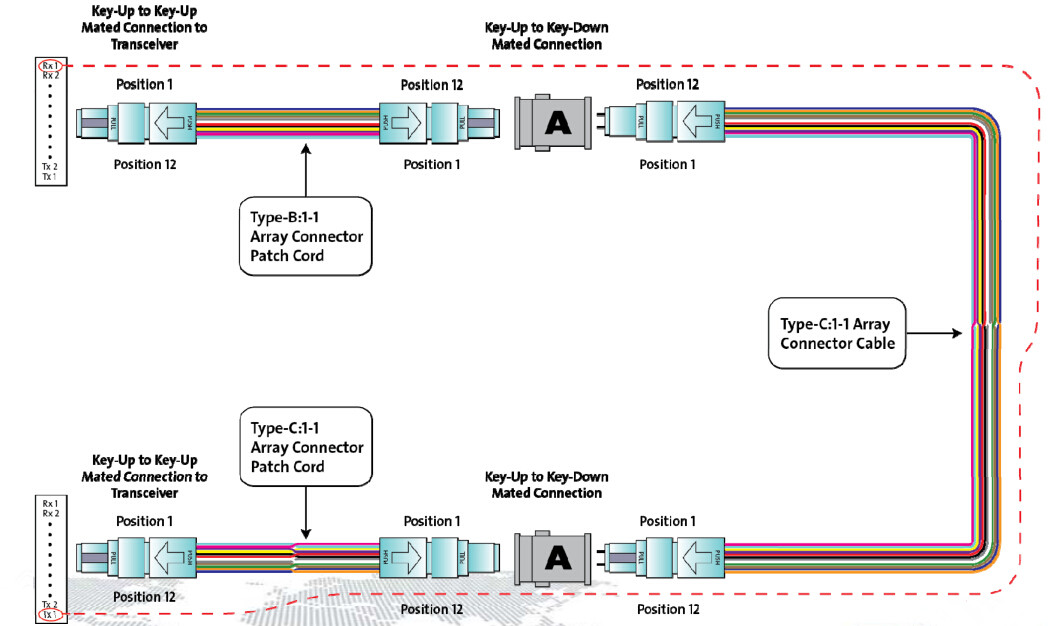
As we know, the purpose of array connectivity methods is to create an optical path from the transmit port of one device to the receive port of another device. Different polarity methods to accomplish this goal may be implemented. However, these different methods may not be inter-operable. Any connectivity method requires a specific combination of components to maintain polarity. Figure 1 illustrates the corresponding connectivity methods A, B and C to establish polarity for parallel signals using an MPO transceiver interface with one row of fibers.

MTP/MPO polarity methods for parallel signals 

Figure 1: Polarity Methods A, B, C for Parallel Signals

Compared with polarity methods for duplex signals, there are two differences for parallel signals. First, the MTP/MPO cassettes for duplex signals are replaced with MPO-to-MPO adapters for parallel signals. Second, the duplex fiber patch cords for duplex signals are replaced with 12-fiber patch cords for parallel signals. For the details about the polarity differences between duplex signals and parallel signals, you can read “Type A MTP Cassette and Type B MTP Cassette: When and Where to Use?” to know more information about polarity methods for duplex signals. While for polarity methods for parallel signals, keep reading this post for more information.

Connectivity Method A for Parallel Signals
 
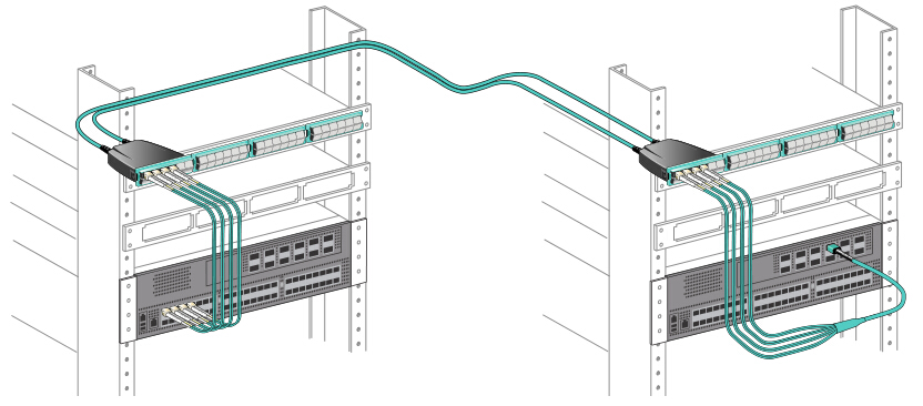
When connecting arrays for parallel signals, the Type A backbone is connected on each end to a patch panel. On one end of the optical link, a Type A array patch cord is used to connect patch panel ports to their respective parallel transceiver ports. On the other end, a Type B array patch cord is used to connect panel ports to their respective parallel transceiver ports. In each optical path, there shall be only one Type B array patch cord.

connectivity method A for parallel signals 

Figure 2: Connectivity Method A for Parallel Signals

Connectivity Method B for Parallel Signals
 
When connecting parallel signals, the Type B backbone is connected on each end to a patch panel. Type B array patch cords are then used to connect the patch panel ports to their respective parallel transceiver ports.

connectivity method B for parallel signals 

Figure 3: Connectivity Method B for Parallel Signals

Connectivity Method C for Parallel Signals
 
Connectivity Method C for parallel signals is similar to connectivity method A. The differences are Type C trunk cable is used instead of Type A, and a Type C cross-over patch cord is required at one end and at the other end, still Type B patch cable used.

connectivity method C for parallel signals 

Figure 4: Connectivity Method C for Parallel Signals

Connection Tips
 
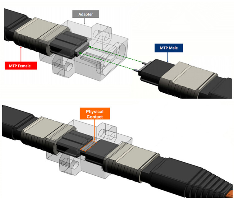
An important point to remember is that MPO plugs use alignment pins. MPO transceivers typically have pins (Male) and the patch cords from transceiver to patch panel are typically unpinned (Female) on both ends. Transitions (mounted behind the panel) are typically pinned (Male) on both ends. Cables from rack to rack are typically unpinned (Female) on both ends.

connection tips for parallel signals 

Figure 5: focused on the connection

The physical contact area is the critical joining point in the fiber network. If there is not a clean physical connection, the light path is disrupted and the connection is compromised.

Conclusion
 
No matter for duplex signals or for parallel signals, there are three types of polarity methods A, B and C. Parallel optical fiber links integrate multiple transmitters in one transmitter module, multiple fibers in fiber array connectors, and multiple receivers in one receiver module. When mating connectors that use alignment pins, it is critical that one plug is pinned and the other plug is unpinned. Typically, the pinned connector is located inside the panel. In other words, the fixed connector is pinned and the connector that is frequently removed and handled in unpinned. Hope the information in this article can help you better understand the MTP/MPO polarity methods for parallel signals.