2016年4月29日星期五

Hot 100G Fiber Optic Transceivers for Data Center

With the increasing demands for higher speeds, and greater scalability, many service provider networking environments and enterprise data centers are undergoing an infrastructure transformation to get higher levels of performance and reliability. As speed and performance needs increase, optical transceivers have become an integral part of overall system design. And then 40G and 100G fiber optic transceiver have become preferable choices for more and more data centers as 1G and 10G cannot meet the needs of the bandwidth-hungry applications. Adopting 100G transceivers not only accelerates data flow throughout your data center or enterprise, but also provides CAPEX (capital expenditures), OPEX (operating expenditures) and time savings. This article focuses on the hot 100G transceiver modules for data centers.

100G CFP/CFP2/CFP4

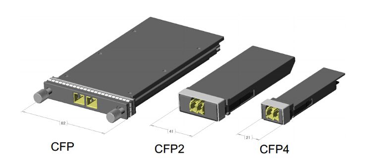
When the IEEE finished the first 100G standard for Ethernet networks, the transceiver industry launched an alphabet soup of form factors. The CFP emerged first, "C" for 100, and FP for "Form factor, Pluggable". The CFP transceiver is specified by MSA between competing manufacturers. The CFP was designed after SFP interface, but is significantly larger to support 100 Gbit/s. While the electrical connection of a CFP uses 10 x 10 Gbit/s lanes in each direction (RX, TX), the optical connection can support both 10 x 10 Gbit/s and 4 x 25 Gbit/s variants of 100 Gbit/s interconnects.

With improvements in technology allowing higher performance and higher density, the development of the CFP2 and CFP4 specifications appeared. While electrical similar, the CFP2 and CFP4 specify a form-factor of 1/2 and 1/4 respectively in size of the CFP. The three modules are not interchangeable, but would be inter-operable at the optical interface with appropriate connectors.
100G CFP

100G QSFP28 Transceiver

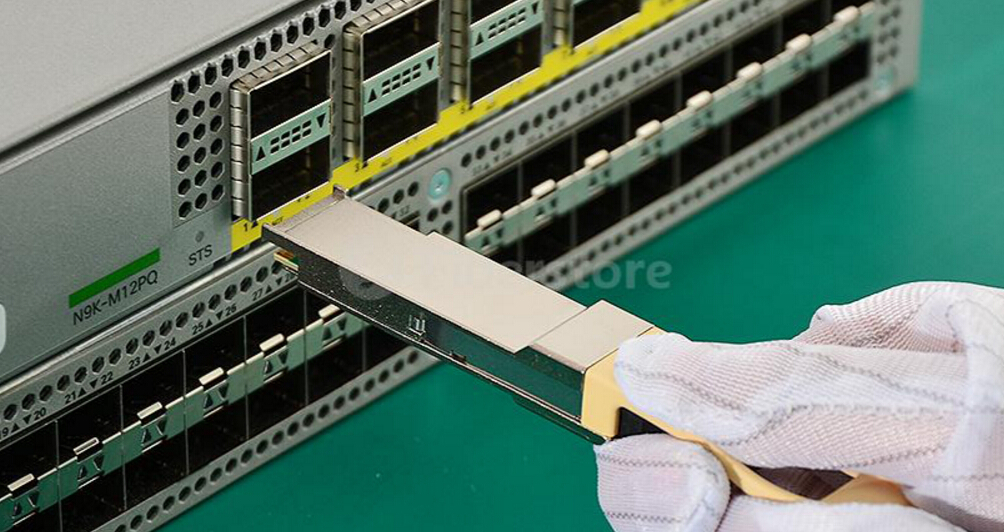
The QSFP28 is the exact same footprint as the 40G QSFP+. The "Q" is for "Quad". Just as the 40G QSFP+ is implemented using four 10 Gbit/s lanes, the 100G QSFP28 is implemented with four 25 Gbit/s lanes. With an upgraded electrical interface to support signaling up to 28 Gbit/s signals, the 100G QSFP28 makes it as easy to deploy 100G networks as 10G networks. When compared to any of the other alternatives, the 100G QSFP28 increases density and decreases power and price per bit. So it is fast becoming the universal data center form factor for the following reasons.

The QSFP28 increases front-panel density by 250% over QSFP+. The form factor is the same and the maximum number of ports is the same, but the lane speeds are increased from 10 Gbit/s to 25 Gbit/s. The increase in panel density is even more dramatic when compared to some other 100 Gbit/s form factor: 450% versus the CFP2.

The QSFP28 transceivers can be based on either VCSELs (for shorter distances on multimode fiber) or silicon photonics (for longer distances on single-mode fiber). The advent of silicon photonics enables QSFP28 transceivers to support any data center reach up to 2 km or more. Silicon photonics provides a high degree of integration.

QSFP28 transceiver

Fiberstore 100G Transceiver Solution

As a professional manufacturer and supplier in optical communication industry, Fiberstore provides a complete range of 100G fiber optic transceivers to meet the potential requirements. We have already prepared the stock of the CFP and CFP2 modules, which can be shipped immediately after ordering. For 100G QSFP28 transceivers, we have 100GBASE-SR4 QSFP28 and 100GBASE-LR4 QSFP28 transceivers. With our serious cost control, the prices of all our 100G fiber optic transceivers are much more affordable than the similar products in the market. Furthermore, with the mature coding technology, they can be compatible with many major brands. For more details, please visit www.fs.com or contact over sales@fs.com.

Article source: www.fiberopticshare.com/hot-100g-fiber-optic-transceivers-for-data-center.html
2016年4月13日星期三

Why Does AOC Meet With Great Favor in 40G Network?

Nowadays more and more data centers are deploying 40G Ethernet links due to the growing need for higher network bandwidth. A variety of technologies and solutions can be chosen for 40G transmission, which includes 40G QSFP+ transceivers, 40G direct attach cables (DACs) and 40G active optical cables (AOCs). All of the three are used to achieve 40G interconnections in data center, and 40G AOCs are very popular and have a broad prospect. Actually, AOCs are widely used in many fields and play an important role in promoting the traditional data center to step into optical interconnection. This article will explain why AOCs meet with great favor in 40G Network.

Definition of AOC
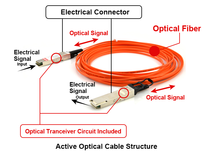
AOC is a type of optical transceiver assemblies terminated with transceiver-style plugs to be used in the same ports where optical transceivers are inserted. 40G AOC can be terminated with 40G QSFP+ connector on one end and on the other end, besides QSFP+ connector, it can be terminated with SFP+ connectors and LC connectors. Moreover, 40G AOC is a 4-channel parallel active optical cable and each channel is able to transmit data at 10Gb/s per direction, providing an aggregated rate of 40Gb/s over multimode fiber ribbon cables. AOCs incorporate active electrical and optical components to boost and receive signal via optical fiber. And they are embodied the latest technology capable of providing the highest data rates.

AOC
What Makes AOC Popular?
Using electrical-to-optical conversion on the cable ends to improve speed and distance performance of the cable without sacrificing compatibility with standard electrical interfaces, the active optical cables are becoming one of the most popular cabling solutions in the data center space. The reasons are as follows.

Lower Cost
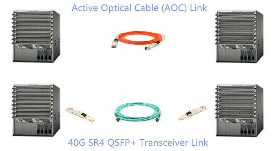
Compared with 40G QSFP+ transceivers, the 40G AOCs are much more cost-effective solutions for the data center. First, the QSFP+ transceivers terminated to the cable are cheaper than the 40G QSFP+ transceivers because there are no lasers in the terminated transceivers. The lasers in the transceivers are very expensive. Second, the AOC eliminates the separable interface between transceiver module and fiber cable. This means that the transceivers are permanently attached to the fiber cables and no fiber optic patch cables are needed. The 40G QSFP+ transceivers need to be used with fiber optic patch cables which may be expensive (see the picture below). Third, AOCs can provide protection from environmental pollutants and other user trouble during installation due to no air holes between the fiber optic transceivers and cables.

active optical cable
Higher Performance With Lighter Weight
As is known to all, DACs are heavy, bulky and require significantly higher power, which makes it difficult to physically manage the data center. And the nature of electrical signals and electromagnetic interface (EMI) also limits DAC’s performance and reliability. However, AOCs are originally invented to replace copper technology and to facilitate high-speed data connectivity for storage, networking, and high-performance computing (HPC) applications. They have lighter weight, a smaller size, EMI immunity, a lower interconnection loss, and reduced power requirements.

More User-friendly
AOCs consist of a complete fiber-optic data link (transceivers plus cable) that can be plugged into existing ports, which enables a very rapid introduction of optical connections. Moreover, the AOCs can provide users with access to all the great advantages of fiber in a plug-in format, such as high bandwidth, relatively thin, light-weight cable and so on. Used in a largely electrical data communications infrastructure, AOCs enable the end users to literally plug into the power and security of a fiber-optic link without any special knowledge of fiber optics.

Summary
With lower cost, higher performance and lighter weight, the AOC meets with great favor in 40G network. It is one of the best solutions to quicker and efficient communication systems. Fiberstore supplies a wide range of solutions for 40G network including the 40G QSFP+ transceivers, 40G DACs and AOCs. The AOCs are highly recommended to be used in data center interconnections. Futhermore, all of our optical assemblies are tested in original-brand switch to ensure the 100% compatibility to your device.

Article source: www.fiberopticshare.com/1813.html

2016年4月8日星期五

Fiber Optic Cable and Connector Cleaning Guide

Why Is Fiber Optics Cleaning Important? 
Reliable and efficient fiber installations are critical to the high performance network. Cleaning fiber optic components is essential for quality connections between fiber optic equipment. It is one of the most basic and important procedures for the maintenance of fiber optic systems, because any contamination in the fiber optic connection will cause failure of the component or failure of the whole system. Some basic cleaning procedures for fiber optic cable and connector will be described in this article.

Fiber Optic Connector Cleaning Steps
Step 1: Inspect the fiber optic connector, component, or bulkhead with a fiberscope.

Step 2: If the connector is dirty, clean it with a dry cleaning technique.

Dry cleaning: Using a reel-based cassette cleaner (see the picture below) with medium pressure, wipe the connector end face against a dry cleaning cloth (single swipe per exposure) in one direction. For angled physical contact (APC) polished connectors, ensure that the entire end face surface mates with the cleaning cloth. Dry cleaning will generally remove airborne contamination and should be attempted first. Inspect the connector end face for contamination after cleaning.

cassette cleaner

Step 3: Inspect the connector.

Step 4: If the connector is still dirty, repeat the dry cleaning technique.

Step 5: Inspect the connector.

Step 6: If the connector is still dirty, clean it with a wet cleaning technique followed immediately with a dry cleaning in order to ensure no residue is left on the end face.
Wet cleaning: Lightly moisten a portion of a lint free wipe with fiber optic cleaning solution (or > 91% Isopropyl Alcohol) and applying medium pressure, first wipe the end face against the wet area and then onto a dry area to clean potential residue from the end face. For APC polished connectors, ensure that the entire end face surface mates with the cleaning wipes. Wet cleaning is more aggressive than dry cleaning, and will remove airborne contamination as well as light oil residue and films.

Step 7: Inspect the connector again.

Step 8: If the contaminate still cannot be removed, repeat the cleaning procedure until the end face is clean.

Note: Never use alcohol or wet cleaning without a way to ensure that it does not leave residue on the end face. Or it will cause equipment damage.

Fiber Optic Patch Cords Cleaning Steps
Step 1: Make sure that the lasers are turned off before you begin the inspection.

Warning: Invisible laser radiation might be emitted from disconnected fibers or connectors. Do not stare into beams or view directly with optical instruments.

Step 2: Remove the protective end cap and store it in a small resealable container.

Step 3: Inspect the connector with a fiberscope.

Step 4: If the connector is dirty, clean with a cartridge or pocket cleaner.

Reminder: For cartridge cleaners, press down and hold the thumb lever. The shutter slides back and exposes a new cleaning area. For pocket cleaners, peel back protective film for one cleaning surface. For manual advance cleaners, pull on the cleaning material from the bottom of the device until a new strip appears in the cleaning window.

Step 5: Hold the fiber tip lightly against the cleaning area.

Reminder: For single, non−APC fiber connectors, rotate the fiber once through a quarter turn, 90 degrees. For APC connector end faces, hold cleaning area at the same angle as the end face.

Step 6: Pull the fiber tip lightly down the exposed cleaning area in the direction of the arrow or from top to bottom.

Warning: Do not scrub the fiber against the fabric or clean over the same surface more than once. This can potentially contaminate or damage your connector.

Step 7: Release the thumb lever to close the cleaning window, if you use cartridge type cleaners.

Step 8: Inspect the connector again with the fiberscope.

Step 9: Repeat the inspection and cleaning processes, as necessary.

Warning: Throw away any used cleaning material, either cards or material cartridges, after use.

Summary
As cleaning is important for fiber optic network, choose the suitable cleaning tools for the fiber optic connectors and fiber optic patch cords would be significant. Fiberstore has various fiber optic cleaning tools, such as pen cleaner, cassette cleaner, etc. All of these cleaning tools are with high quality and reasonable price. Moreover, most of them are in stock. You can enjoy the same day shipping after order. Contact sales@fs.com or visit www.fs.com for more detailed information.

Article source: www.fiberopticshare.com/fiber-optic-cable-and-connector-cleaning-guide.html