2016年3月29日星期二

Cabling Solutions for 1 GbE and 10 GbE

Ethernet technology has continually evolved in order to meet the never-ending requirement for faster rates of data transmission. The demand for faster application speeds has also spurred technological evolution on data carrying techniques. As such, copper and fiber transmission standards have progressed, providing greater bandwidth for transporting data over Ethernet architectures with reduced cost and complexity. This article highlights the cabling solutions for 1 Gigabit Ethernet and 10 Gigabit Ethernet.
 
1 Gigabit Ethernet Cabling
 
For 1 Gigabit Ethernet cabling, both fiber and copper cable connections are available.

Fiber Cabling
 
The optical fiber cables are usually used for longer connections. Optical fiber connections are constructed with a combination of a transceiver, which receives digital signals from the Ethernet device (switch or adapter card) and converts them to optical signals for transmission over the fiber. The most widely used transceiver for 1 Gigabit Ethernet is SFP (small form factor pluggable). For instance, the Cisco GLC-LH-SMD 1000BASE-LX/LH SFP can support transmission distance up to 10 kilometers.

The difference in cable choices comes from the distance limitations encountered with the various types of optical transmission. Short range and long range are the two different commonly available types. Short range supports connections of up to 550 meters, while long range supports connections of up to 10 kilometers. Multimode fiber cables are typically used for short range transmission and single-mode fiber cables are used for long range transmission.

The final consideration on the fiber cable is the connector type. The main differences among types of connectors lie in dimensions and methods of mechanical coupling. Multimode fiber cables and single-mode fiber cables require different connectors. SC and LC connectors are the most common types.

Copper Cabling
 
For copper cables supporting 1 Gigabit Ethernet, the Category 5 unshielded twisted pair (Cat5-UTP) is utilized. With a RJ45 connector on either end, Cat 5 can support connections of up to 100 meters. Cat5e, an enhanced version of the Category 5, is the most used Ethernet cabling today. For lower speed (10 or 100 Mbps) connections, only two of the four pairs in Cat 5 cables are used. For 1 Gigabit Ethernet, all four pairs are used. The following picture shows the 1G and 10G application in an enterprise data center.
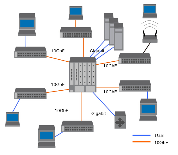
1G and 10G
 
10 Gigabit Ethernet Cabling
 
For 10 Gigabit Ethernet cabling, the cabling choices are nearly the same with the 1 Gigabit Ethernet. The fiber options are very similar. The transceivers are somewhat different.

Fiber Cabling
 
An enhanced version of the SFP transceivers was standardized for use with 10 Gigabit Ethernet and named SFP+ (enhanced small form factor pluggable). SFP+ has the same mechanical characteristics as the SFP transceiver. It is capable of supporting the higher speed—10 Gbps. Besides SFP+ transceiver, XFP (10 Gigabit small form factor pluggable) transceiver also can support 10 Gigabit Ethernet. Compared with XFP, the SFP+ has smaller form factor allowing for much more dense packaging of ports on switches. Moreover, the direct attach copper cable, supporting 10Gbps Ethernet data transmission, has two SFP+ connectors on both end. This 10G direct attach copper cable like Cisco SFP-H10GB-CU5M supports transmission distance up to 12-15 meters, which is often more than enough for interconnecting systems in racks in data centers. With these two capabilities, SFP+ has become the predominant 10 Gigabit Ethernet connector type.

For 10 Gigabit Ethernet fiber connections, the same optical fiber as 1 Gigabit Ethernet is used. The short range fiber cables can support connections of up to 300 meters and long range fiber cables can support connections of up to 2 kilometers. Besides these two, a new option is also available—extended range (for connections of up to 10 kilometers).

LC and SC are also the common connector types. Note that these cables can be connected to either XFP or SFP+ transceivers. The connector type defines the mechanical specifications of the fiber-to-transceiver interface. Thus, one could have a XFP transceiver on one end of a 10G Ethernet fiber cable and a SFP+ transceiver on the other end. As long as the cable type and connector type match, there is no problem.

Copper Cabling
 
For 10 Gigabit Ethernet cabling, the standards body determined that even the enhanced Cat5e UTP traditional Ethernet cable would not be able to carry the signal reliably for any significant distance. So a new specification, still using RJ45 connectors, was introduced and named 10GBASE-T. This calls for a 4-wire twisted pair cable with even more stringent limitations on cross-talk. It is called Cat 6a. 10GBASE-T cables for up to 100 meters are supported.

Summary
 
For 1 Gigabit Ethernet connection, SFP transceiver, fiber optic cables and copper cables are the choices. For 10 Gigabit Ethernet connection, 10G SFP+, 10G XFP, optical fiber cables as well as copper cables are able to meet the requirements. Fiberstore, a professional company in the field of optical network devices and interconnection, supplies various fiber optic transceivers, fiber optic cables and copper cables. Lots of the fiber optic products, such as SFP-10G-ER SFP+, have large inventory and low price. For more detailed information about us, please visit www.fs.com.

Article source: www.fiberopticshare.com
2016年3月23日星期三

Introduction to DDM Function of GLC-LH-SMD Transceiver

Basic Introduction

As is known to all, Cisco GLC-LH-SMD is the replacement of GLC-LH-SM. It consists five parts: the LD driver, the limiting amplifier, the digital diagnostic monitor, the 1310nm FP laser and the PIN photo-detector. Supporting a data rate of 1.25 Gbps, this GLC-LH-SMD SFP transceiver operates on standard single-mode fiber optic link spans of up to 10 km and up to 550 m on any multimode fibers. You may say the letter “D” is the only difference between the two, and ask what’s the meaning of “D” and why GLC-LH-SMD can take the place of GLC-LH-SM? This article will give you an answer by introducing its additional function—DDM (digital diagnostic monitoring).

What Is DDM?

Actually, the letter “D” stands for the digital diagnostic monitoring function according to the industry standard multi-source agreement (MSA) SFF-8472 and is known as digital optical monitoring (DOM). A fiber optic transceiver with DDM is higher end than the one without DDM function. The DDM function gives end users the ability to monitor real-time parameters of the optical transceivers, such as the transceiver temperature, laser bias current, transmitted optical power, received optical power and transceiver supply voltage. Most of today’s fiber optic transceivers have this function.

Functions of DDM

After knowing what digital diagnostic monitoring is, next we’d move to the functions of DDM or what DDM can actually do. Literally, DDM is able to provide component monitoring on transceiver applications in details like the real-time parameters listed in the previous paragraph. But that’s not all functions of DDM. The SFF-8472 added DDM interface and outlined that DDM interface is an extension of the serial ID interface defined in GBIC specification and the SFP MSA. This DDM interface defines a sophisticated system of alarm and warning flags, which alerts end users when particular operating parameters are inconsistent with the factory-set normal range. So the DDM interface is also able to let the end users have the ability to achieve fault isolation and failure prediction. The three functions (component monitoring, fault isolation, failure prediction) will be stated in more details below.

Component Monitoring

Component monitoring is the most familiar function to users. Usually the key parameters of the optical transceivers—transceiver temperature, transceiver supply voltage, laser bias current, transmit average optical power and received optical modulation amplitude (OMA) or average optical power, will be monitored. If the transceiver’s specified operating limits are exceeded and compliance cannot be ensured, these real-time diagnostic parameters will alert the system.

Fault Isolation

Fault isolation is the second function of DDM. The DDM is able to isolate the particular location of fault in an optical network system. With the combination of the DDM interface status flags, transceiver hard pins and diagnostic parametric monitor data, it’s easy to pinpoint the specific location and cause of a link failure.

Failure Prediction

Failure prediction is the last function of DDM. Based on the transceiver parametric performance, the DDM can be helpful in failure prediction on fiber optic links. Device faults and high error rate conditions are the two basic types of failure conditions which can be seen on optical transceivers. Device fault means non-operation or malfunction. With the nature of semiconductor lasers, this is usually applied to transmitter performance. High error rate conditions refer to the operating conditions that transceiver is operating at its signal-to-noise limit. This is typically applied to optical fiber performance.


GLC-LH-SMD


Summary

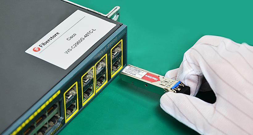
After reading the above statement, have you got a better understanding about the DDM function of GLC-LH-SMD? Fiberstore’s GLC-LH-SMD small form factor pluggable (SFP) transceiver is compatible with the small form factor pluggable multi-source agreement (MSA). This transceiver is programmed to be fully compatible and functional on a wide range of Cisco equipment. All Cisco compatible GLC-LH-SMD 1000BASE-LX/LH SFP transceivers from Fiberstore are all tested on Cisco original equipment to ensure their superior quality and performance (see the picture above). Besides the GLC-LH-SMD SFP transceiver, many other Cisco compatible transceivers provided by Fiberstore, such as SFP-10G-LR and QSFP-40G-CSR4, have to be tested before arriving to customers. For more detailed information about us, please visit www.fs.com or contact over sales@fs.com.

2016年3月14日星期一

Introduction to MPO Fiber Testing

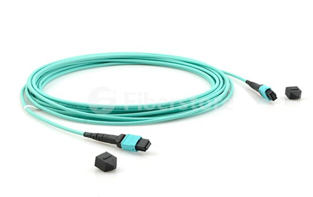
MPO trunk cables (see the picture below) have become the common cabling solution for the ever increasing data center bandwidth requirements. The MPO fiber cable links have the features of parallel transmission and they are compact, pre-terminated, able to handle bandwidth all the way up to 100 Gbps, and even plug and play by design. The testing, certification and migration of the MPO fiber cables could be a nightmare though they have these advantages. This article will focus on the MPO cables testing in the data center.
MPO trunk cables

The standard testing process of fiber cables can be time consuming, error prone, and once you throw polarity of all 12 fiber connections into the mix, almost a hit-and-miss manual affair. And if you migrate from 10 Gbps to 40/100 Gbps, you need to test and validate performance all over again.

Challenges of MPO Cables 
In order to get a better understanding about the challenges of MPO cable validation, it is essential to understand MPO cables and how they are tested. An MPO connection is about the size of a fingernail and contains 12 optical fibers, each less than the diameter of a human hair, and each one needs to be tested separately. The actual fiber test is quick enough, typically under 10 seconds per fiber once you’re in process.

The challenge is that pre-terminated fiber is only guaranteed good as it exists in the manufacturer’s factory. It must then be transported, stored, and later bent and pulled during installation in the data center. All kinds of performance uncertainties are introduced before fiber cables are deployed. Proper testing of pre-terminated cables after installation is the only way to guarantee performance in a live application. Testing and determining fiber polarity is another challenge. The simple purpose of any polarity scheme is to provide a continuous connection from the link’s transmitter to the link’s receiver. For array connectors, TIA-568-C.0 defines three methods to accomplish this: Methods A, B and C. Deployment mistakes are common because these methods require a combination of patch cords with different polarity types.

More Bandwidth, More Testing
The use of MPO cables for trunking 10G connections in the data center has steadily risen over the past years. That trunking requires use of a cassette at the end of the MPO cable designed to accommodate legacy equipment connections. Now the 40G and 100G connections are coming on the market. So a migration path has emerged: remove the 10G cassette from the MPO cable and replace it with a bulkhead accommodating a 40G connection. Then it might be possible to remove that bulkhead and do a direct MPO connection for 100 Gbps.

The problem is that while this migration strategy is an efficient way to leverage the existing cabling, in comparison to 10G connection, the 40G and 100G standards call for different optical technology (parallel optics) and tighter loss parameters. In all, you need to verify the links to ensure the performance delivery the organization requires when you have a migration for your network.

Proper MPO Testing
What would a proper MPO test look like? The answer is simple. Test all 12 fibers—the whole cable—simultaneously and comprehensively (including loss, polarity). That sort of test capability changes the fiber landscape, enabling installers and technicians to efficiently validate and troubleshoot fiber—flying through the process by tackling an entire 12-fiber cable trunk with the push of a button.
The tools to perform this type of test are emerging on the market, and promise to reduce the time and labor costs up to 95% over individual fiber tests. Characteristics to look for in such a tool include the following parts.

  • An onboard MPO connector to eliminate the complexity and manual calculations associated with a fan-out cord.
  • A single "Scan All" test function that delivers visual verification via an intuitive interface for all 12 MPO fibers in a connector.
  • Built-in polarity verification for end-to-end connectivity of MPO trunk cables.
  • "Select Individual Fiber" function that enables the user to troubleshoot a single fiber with more precision.

Demand for fast and reliable delivery of critical applications is driving data center technology to evolve at an ever increasing pace. And the insatiable need for bandwidth ensures that the integrity of the data center has become inextricably linked to the strength of the fiber cabling infrastructure. The growing use of MPO trunk cables means that it’s time to stop the cumbersome verification of individual fibers. After all, it’s a single MPO connection. You should be able to test the MPO connection as a whole.

2016年3月8日星期二

Fiber Types and Associated Optical Transceivers

Definition of Optical Fiber
 
An optical fiber is a flexible filament of very clear glass capable of carrying information in the form of light. Optical fibers are hair-thin structures created by forming pre-forms, which are glass rods drawn into fine threads of glass protected by a plastic coating. Fiber manufacturers use various vapor deposition processes to make the pre-forms. The fibers drawn from these pre-forms are then typically packaged into cable configurations, which are then placed into an operating environment for decades of reliable performance.

Anatomy of Optical Fiber
 
Core and cladding are the two main elements of an optical fiber. The core, made of silica glass, is the light transmission area of the fiber. Sometimes it may be treated with a “doping” element to change its refractive index and therefore the velocity of light down the fiber. The cladding is the layer completely surrounding the core. The difference in refractive index between the core and cladding is less than 0.5 percent. The refractive index of the core is higher than that of the cladding, so that light in the core strikes the interface with the cladding at a bouncing angle, gets trapped in the core by total internal reflection, and keeps traveling in the proper direction down the length of the fiber to its destination.

Surrounding the cladding is usually another layer, called coating, which typically consists of protective polymer layers applied during the fiber drawing process, before the fiber contacts any surface.
optical fiber
Fiber Types and Associated Optical Transceivers
 
Fiber designs that are used today include single-mode and multimode fiber. Multimode fiber simply refers to the fact that numerous modes of light rays are carried simultaneously through the waveguide. Multimode fibers used in telecom or datacom applications have a core size of 50 or 62.5 microns. Single-mode fiber shrinks the core down so small that the light can only travel in one ray. The typical core size of a single-mode fiber is 9 microns.

Multimode Transceiver and Fiber Type Compatibility Matrix
 
The table below summarizes various optical interfaces and their performance over the different fiber types. The table is directly derived from the IEEE 802.3-2005 standard and specifies the maximum reach achievable over each fiber type and the requirement for a mode conditioning patch cord (MCP).
 
Interface Type
Wavelength (nm)
Fibers Supported
Reach (m)
MCP Requirement
1000BASE-SX
850
FDDI-grade
220
No
OM1
275
No
OM2
550
No
OM3
Not specified
1000BASE-LX
1300
FDDI-grade
550
Yes
OM1
550
Yes
OM2
550
Yes
OM3
Not specified
10GBASE-SR
850
FDDI-grade
26
No
OM1
33
No
OM2
82
No
OM3
300
No
10GBASE-LX4
1300
FDDI-grade
300
Yes
OM1
300
Yes
OM2
300
Yes
OM3
Not specified
10GBASE-LRM
1300
FDDI-grade
220
Yes
OM1
220
Yes
OM2
220
Yes
OM3
220
No

These performance levels are guaranteed. If we go beyond the standard, longer reaches may be achievable depending on the quality of each link. Fiber quality can vary for a specific type due to the aging factor or to the random imperfections it was built with. In order to really know if a link can work, the rule is to try and see if the performance is satisfactory. The link should be either error-free for critical applications, or the bit error should remain below 10-12 as per minimum standard requirement.

For example, it may be possible to reach much longer distances than 550 m with an OM3 laser-optimized fiber and 1000BASE-SX interfaces. Also, it may be possible to reach 2 km between two 1000BASE-LX devices over any fiber type with mode conditioning path cords properly installed at both ends.

Single-mode Transceiver and Fiber Type Compatibility Matrix
 
The reaches in the table below illustrate typical performance observed in the field. They may vary with the rate and fiber type and should not be considered as guaranteed. NDSF refers to non-dispersion shifted fiber. DSF means dispersion shifted fiber with a zero dispersion centered at 1550 nm, while NZDSF means non-zero dispersion shifted fiber with a zero dispersion usually centered at 1510 nm.
 
Interface Type
Wavelength (nm)
Typical Reach* (km)
NDSF
DSF
NZDSF
1000BASE-LX
1000BASE-BX
10GBASE-LR
10GBASE-LW
10GBASE-LX4
1310
10
Yes
No
No
10GBASE-ER
1550
30-40
Yes
Yes
Yes
1000BASE-ZX
10GBASE-ZR
1550
80-100
Yes
Yes
Yes
CWDM
1470 to 1610
80-120**
Yes
No
Yes
DWDM
1530 to 1565
80-100**
Yes
No
Yes
 
Conclusion
 
Fiber optic cables are the medium of choice in telecommunications infrastructure, enabling the transmission of high-speed voice, video and data traffic in enterprise and service provider networks. This article has briefly explained optical fiber basis and its structure as well as the associated transceivers by the fiber types. As a professional supplier in optical industry, Fiberstore has all kinds of transceivers, such as SFP-10G-ER, GLC-LH-SMD, etc. And Fiberstore also provides customized service according to your special requirements.

Article source: www.fiberopticshare.com/1777.html

2016年3月2日星期三

Instructions for 40G QSFP+ Transceiver Installation and Removing

As is know to all, 40G QSFP+ transceiver modules are hot-swappable, parallel fiber-optical modules with four independent transmit and receive channels. These channels can terminate in another 40G QSFP+ transceiver, or the channels can be broken out to four separate 10G SFP+ transceivers. QSFP+ transceiver modules connect the electrical circuitry of the system with either a copper or an optical external network. And the transceiver, such as QSFP-40G-SR4, is used in short reach applications like switches, routers and data center equipment where it can provide higher density than SFP+ modules. This article will provide the instructions for the 40G QSFP+ transceiver installation and removing.

Required Tools
Three tools are needed to install the 40G QSFP+ transceiver modules. The first one is a wrist strap or other personal grounding device to prevent ESD (electro-static discharge) occurrences. The second one is an antistatic mat or antistatic foam to set the transceiver on. The last one is fiber-optic end-face cleaning tools and inspection equipment.

Installing 40G QSFP+ Transceivers Modules
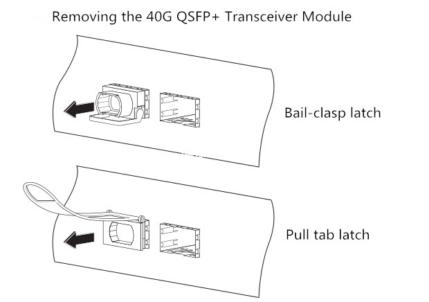
QSFP+ transceivers have either a bail-clasp latch or a pull-tab latch. Installation procedures for both types of latches are provided.

Note: The QSFP+ transceiver module is a static-sensitive device. Always use an ESD wrist strap or similar individual grounding device when handling QSFP+ transceiver modules or coming into contact with system modules.

Follow the steps below to install a QSFP+ transceiver.

Step 1: Attach an ESD wrist strap to yourself and a properly grounded point on the chassis or the rack.

Step 2: Remove the QSFP+ transceiver module from its protective packaging.

Step 3: Check the label on the QSFP+ transceiver module body to verify that you have the correct model for your network.

Step 4: For optical QSFP+ transceivers, remove the optical bore dust plug and set it aside.

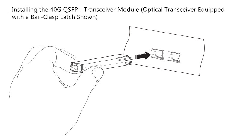
Step 5: For transceivers equipped with a bail-clasp latch, first keep the bail-clasp aligned in a vertical position. Second align the QSFP+ transceiver in front of the module’s transceiver socket opening and carefully slide the QSFP+ transceiver into the socket until the transceiver makes contact with the socket electrical connector.
40G QSFP+
Step 6: For QSFP+ transceivers equipped with a pull-tab latch, first hold the transceiver so that the identifier label is on the top. Second align the QSFP+ transceiver in front of the module’s transceiver socket opening and carefully slide the QSFP+ transceiver into the socket until the transceiver makes contact with the socket electrical connector.

Step 7: Press firmly on the front of the QSFP+ transceiver with your thumb to fully seat the transceiver in the module’s transceiver socket.

Step 8: For optical QSFP+ modules, reinstall the dust plug into the QSFP+ transceivers optical bore until you are ready to attach the network interface cable. Do not remove the dust plug until you are ready to attach the network interface cable.

Attaching the Optical Network Cable
Note: Before removing the dust plugs and making any optical connections, please remember the following guidelines.

Firstly, keep the protective dust plugs installed in the unplugged fiber-optic cable connectors and in the transceiver optical bores until you are ready to make a connection. Secondly, inspect and clean the MPO connector or the duplex LC connector end faces before making any connections. Thirdly, grasp the MPO or the duplex LC connector only by the connector housing to plug or unplug a fiber-optic cable.

Follow the steps below to attach the optical cables.

Step 1: Remove the dust plugs from the optical network interface cable MPO connectors. Save the dust plugs for future use.

Step 2: Inspect and clean the MPO or duplex LC connector’s fiber-optic end faces.

Step 3: Remove the dust plugs from the QSFP+ transceiver module optical bores.

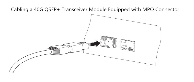
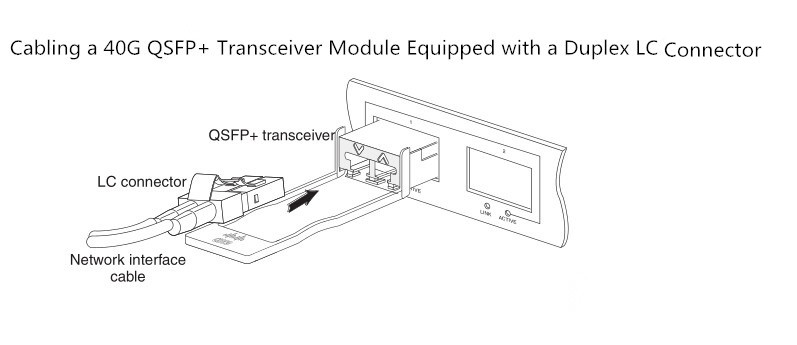
Step 4: Immediately attach the network interface cable MPO connector or duplex LC connector to the QSFP+ transceiver module.
QSFP+ transceiver
LC connector
Step 5: Verify that the optical network cable is fully seated by pulling gently on the cable’s MPO or duplex LC connector boot. If the network cable disconnects, reinstall it and make sure that the cable connector is fully seated and that the connector latch engages.

Removing 40G QSFP+ Transceiver Modules
Follow the steps below to remove a QSFP+ transceiver.

Step 1: For optical QSFP+ transceivers, disconnect the network interface cable from the QSFP+ transceiver connector.

Step 2: For QSFP+ transceivers equipped with a bail-clasp latch, first pivot the bail-clasp down to the horizontal position. Second immediately install the dust plug into the transceivers optical bore. Third grasp the sides of the QSFP+ transceiver and slide it out of the module socket.

40G transceiver
Step 3: For QSFP+ transceivers equipped with a pull tab latch, first install the dust plug into the transceiver’s optical bore immediately. Second grasp the tab and gently pull to release the transceiver from the socket. Third slide the transceiver out of the socket.

Step 4: Place the QSFP+ transceiver into an antistatic bag.

Conclusion
The above statements illustrate how to install a 40G QSFP+ transceiver, attach an optical network cable and remove a QSFP+ transceiver module. It is necessary to know the correct way of installing and removing a QSFP+ transceiver as correct operation can protect the 40G transceiver from being damaged and ensure its stable performance.