2016年12月22日星期四

How Much Do You Know About PM Patch Cables?

When talking about fiber optic patch cables, you may know LC fiber patch cables or MTP/MPO fiber cables. Besides these cables, there are some special fiber patch cables, such as mode conditioning patch cables, which has been introduced in the previous article. Today we will introduce another special fiber patch cable—polarization maintaining (PM) fiber patch cables.

Definition of PM Patch Cables
 
At the very first beginning, let’s check the basic definition about the PM patch cables. PM patch cords are based on a high precision butt-style connection technique. The PM axis orientation is maintained by using male connectors with a positioning key and a bulkhead female receptacle with a tightly toleranced keyway, ensuring good repeatability in extinction ratios and insertion losses.
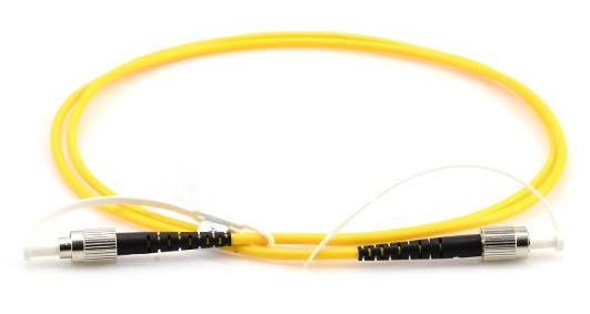
PM patch cables 

Why Need PM Patch Cables?
 
When a normal fiber is bent or twisted, stresses are induced in the fiber and the stresses will change the polarization state of light traveling through the fiber. If the fiber is subjected to any external perturbations, say changes in the fiber’s position or temperature, then the final output polarization will vary with the time. This is true for even short lengths of fiber, and is undesirable in many applications that require a constant output polarization from the fiber.

To solve this problem, PM fibers are developed. These fibers work by inducing a difference in the speed of light for two perpendicular polarizations traveling through the fiber. This birefringence creates two principal transmission axes within the fiber, known respectively as the fast and slow axes of the fiber. Provided the input light into a PM fiber is linearly polarized and orientated along one of these two axis, then the output light from the fiber will remain linearly polarized and aligned with that axis, even when subjected to external stresses. A one meter long connectorized patch cord constructed with PM fiber can typically maintain polarization to at least 30dB at 1550 nm when properly used. Naturally, how well a PM fiber maintains polarization depends on the input launch conditions into the fiber. Perhaps the most important factor is the alignment between the polarization axis of the light with the slow axis of the fiber.

Connectors of PM Patch Cables
 
Given the importance of the alignment of the PM axis across a connection, the choice of connector is especially important. The most common type of PM connector is FC connector which has a positioning key to preserve the angular orientation of the fiber. The industry standard is to align the slow axis of the fiber with the connector key. The tolerances between the key and keyway on standard FC connectors are too loose to accurately maintain angular alignment, so manufacturers have tightened the key dimension tolerances on PM connectors. The key dimensions being used are based on FC angle polished connector (APC) standards. Unfortunately, two APC standards are currently on the market, a narrow, or reduced key design, and a wide key design. The two dimensions are incompatible with one another, so it is important to know beforehand which design you are using. Besides the FC connectors, PM patch cables using other connector types are also available, such as SC connectors. In all cases, there must be a key or similar structure to act as a reference, and tight tolerances must be kept to ensure that the ferrules cannot rotate.

Conclusion
 
PM patch cables are widely used in polarization sensitive fiber optic systems for transmission of light that requires the PM state to be maintained. FS.COM provides polarization maintaining (PM) patch cables with various connector types. For the details, welcome to visit www.fs.com.

2016年11月18日星期五

Mode Conditioning Patch Cables Overview

Fiber optic patch cables play an important role in fiber optic connection. There are numbers of fiber patch cables on the market, ranging from the standard fiber patch cables to special fiber patch cables, such as mode conditioning patch cables, bend insensitive patch cables, traceable fiber patch cables, etc. This article will not introduce all of these fiber jumpers, only focus on the mode conditioning patch cables.
 
Why Need Mode Conditioning Cables?
 
Transceiver optics used in Gigabit Ethernet (1000BASE-LX) launch only single-mode long wave signals (1310 nm). This poses a problem if an existing fiber network utilizes multimode cables. When a single-mode signal is launched into a multimode fiber, the phenomenon known as DMD (differential mode delay) can create multiple signals within the multimode fiber. This effect can confuse the receiver and produce errors. Mode conditioning cables utilize an offset between the single-mode fiber and multimode fiber to eliminate DMD and the resulting multiple signals allowing use of 1000BASE-LX over existing multimode fiber cable system.

What Are Mode Conditioning Fiber Patch Cables?
 
Mode conditioning patch cables are required when Gigabit 1000BASE-LX routers and switches are installed into existing multimode cable plants. They are used to adapt the single-mode output of Gigabit Ethernet (1000BASE-LX) transceivers to a multimode cable network. They are fully compliant with IEEE 802.3z application standards.


Mode conditioning patch cable 

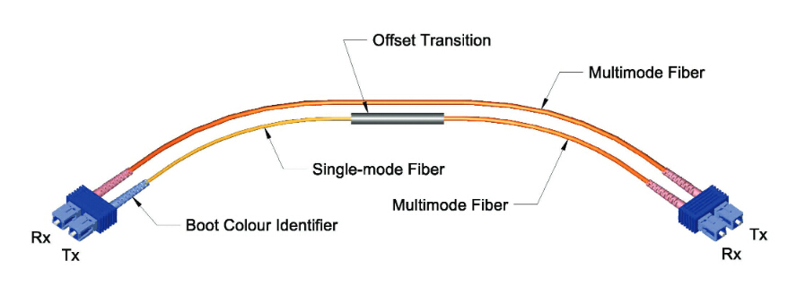
The conditioned channel of mode conditioning patch cables consists of a single-mode fiber which has been fusion spliced to a multimode fiber in an offset manner, with a precise core alignment and angle. The non-conditioned channel of mode conditioning patch cables consists of one length of multimode cable. Light is launched on to the multimode fiber of the conditioned channel at a specific angle, giving the patch cord its mode conditioning properties. The fusion splice is protected by a black over-wrap. The other side has both a multimode and single-mode cable end. This side of the cable connects to the Gigabit transceiver equipment with the single-mode leg connecting to the transmit side. The side has two multimode cable ends connecting to the cable plant.

Things You Should Know When Using Mode Conditioning Patch Cables
 
Use mode conditioning patch cables in pairs. It means that you will need a mode conditioning patch cable at each end to connect the equipment to the cable plant. So then these cables are usually ordered in even numbers. The only reason to order an odd number of mode conditioning cables is to have a spare on hand. Mode conditioning patch cables can only convert single-mode to multimode. If you want to convert multimode to single-mode, then a media converter will be required.

If your Gigabit LX switch is equipped with SC or LC connectors, please be sure to connect the yellow leg (single-mode) of the cable to the transmit side, and the orange leg (multimode) to the receive side of the equipment. It is imperative that this configuration be maintained on both ends. The swap of transmit and receive can only be done at the cable plant side.

Mode conditioning patch cables 

If some customers remain reluctant to deploy MCP cables, and for customers using OM3 or OM4 cables, please measure the power level before plugging the fiber into the adjacent receiver. When the received power is measured above -3dBm (in 1000BASE-LX links), a 5-dB attenuator for 1300 nm should be used and plugged at the transmitter source of the optical module on each side of the link. Actually, OM3/OM4 MCP can also work in this event. While whether all multimode fiber types require mode conditioning, you can contact the manufacturer of your installed cable for the answer.

Summary
 
Mode conditioning patch cables are duplex multimode cords that have a small length of single-mode fiber at the start of the transmission leg. The basic principle behind the cords is that you launch your laser into the small section of single-mode fiber. The other end of the single-mode fiber is coupled to multimode section of the cable with the core offset from the center of the multimode fiber. FS.COM provides various types of mode conditioning patch cables with different connectors. All these mode conditioning patch cables are in high quality and low price. For more details, welcome to visit www.fs.com or contact us over sales@fs.com.

2016年11月10日星期四

Introduction to the Components Used in DWDM System

DWDM is an innovation that enables multiple optical carriers to travel in parallel in a fiber. DWDM devices combine the output from several optical transmitters for transmission across a single fiber. At the receiving end, another DWDM device separates the combined optical signals and passes each channel to an optical receiver. Only one optical fiber is used between DWDM devices (per transmission direction). How DWDM system works, and what components are needed in DWDM system? Keep reading this article and you will find the answer.

Components Used in DWDM System
 
Typically, the components used in a DWDM system include optical transmitters and receivers, DWDM mux/demux, OADM (optical add/drop multiplexers), optical amplifiers and transponders (wavelength converters). Following part will introduce these devices respectively.

Optical Transmitters and Receivers
 
Transmitters are described as DWDM components because they provide the source signals which are then multiplexed. The characteristics of optical transmitters used in DWDM systems is highly important to system design. Multiple optical transmitters are used as the light sources in a DWDM system which requires very precise wavelengths of light to operate without interchannel distortion or crosstalk. Several individual lasers are typically used to create the individual channels of a DWDM system. Each laser operates at a slightly different wavelength.

DWDM Mux/DeMux
 
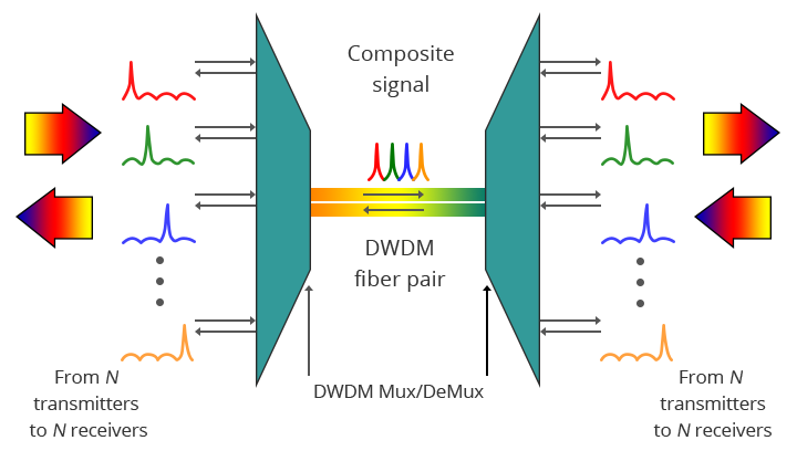
The DWDM Mux (multiplexer) combines multiple wavelengths created by multiple transmitters and operating on different fibers. The output signal of an multiplexer is referred to as a composite signal. At the receiving end, the DeMux (demultiplexer) separates all of the individual wavelengths of the composite signal out to individual fibers. The individual fibers pass the demultiplexed wavelengths to as many optical receivers. Generally, Mux and DeMux components are contained in a single enclosure. Optical Mux/DeMux devices can be passive. Component signals are multiplexed and demultiplexed optically, not electronically, therefore no external power source is required.

DWDM Mux/DeMux 

The picture above shows the bidirectional DWDM operation. N light pulses of N different wavelengths carried by N different fibers are combined by a DWDM Mux. The N signals are multiplexed onto a pair of optical fibers. A DWDM demultiplexer receives the composite signal and separates each of the N component signals and passes each to a fiber. The transmit and receive signal arrows represent client-side equipment. This requires the use of a pair of optical fibers—one for transmit and the other for receive.

OADM
 
OADM is often a device found in WDM systems for multiplexing and routing different channels of fiber into or out of a single-mode fiber (SMF). It is created to optically add/drop one or multiple CWDM/DWDM channels into a few fibers, providing the power to add or drop a single wavelength or multi-wavelengths from a fully multiplexed optical signal. This permits intermediate locations between remote sites gain access to the regular, point-to-point fiber segment linking them. Wavelengths not dropped pass-through the OADM and carry on towards the remote site. Additional selected wavelengths may be added or dropped by successive OADMs if required.

DWDM OADM 

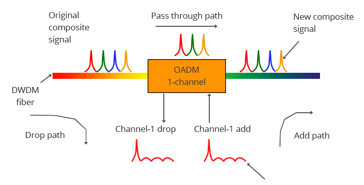
The picture above demonstrates the operation of a one-channel OADM. This OADM is designed to only add or drop optical signals with a particular wavelength. From left to right, an incoming composite signal is broken into two components, drop and pass-through. The OADM drops only the red optical signal stream. The dropped signal stream is passed to the receiver of a client device. The remaining optical signals that pass through the OADM are multiplexed with a new add signal stream. The OADM adds a new red optical signal stream, which operates at the same wavelength as the dropped signal. The new optical signal stream is combined with the pass-through signals to form a new composite signal.

Optical Amplifiers
 
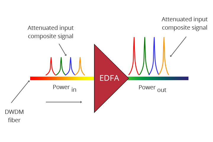
Optical amplifiers boost the amplitude or add gain to optical signals passing on a fiber by directly stimulating the photons of the signal with extra energy. They are “in-fiber” devices. Optical amplifiers amplify optical signals across a broad range of wavelengths, which is very important for DWDM system application.

EDFA 

Transponders (Wavelengths Converters)
 
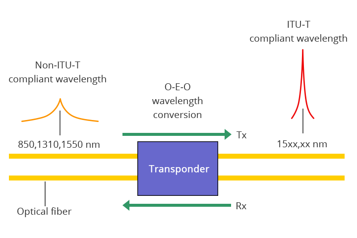
Transponders convert optical signals from one incoming wavelength to another outgoing wavelength suitable for DWDM applications. Transponders are optical-electrical-optical (O-E-O) wavelength converters. A transponder performs an O-E-O operation to convert wavelengths of light. Within the DWDM system, a transponder converts the client optical signal back to an electrical signal (O-E) and then performs either 2R (reamplify, reshape) or 3R (reamplify, reshape and retime) functions.

transponders 

The picture above shows bi-directional transponder operation. A transponder is located between a client device and a DWDM system. From left to right, the transponder receives an optical bit stream operating at one particular wavelength (1310 nm). The transponder converts the operating wavelength of the incoming bit stream to an ITU-compliant wavelength. It transmits its output into a DWDM system. On the receive side (right to left), the process is reversed. The transponder receives an ITU-compliant bit stream and converts the signals back to the wavelength used by the client device.

Summary
 
This article provides some basic information about the components used in a DWDM system. All of the components compose the integrated DWDM system. And they are indispensable. Hope the information in this article is helpful when building your DWDM system.

2016年11月1日星期二

Understanding the Split Ratios and Splitting Level of Optical Splitters

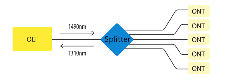
Optical splitters play an important role in FTTH PON networks where a single optical input is split into multiple output, thus allowing a single PON interface to be shared among many subscribers. The optical splitters have no active electronics and don’t require any power to operate. They are typically installed in each optical network between the PON OLT (optical line terminal) and ONTs (optical network terminals) that the OLT serves. Generally, two kinds of fiber optic splitters are popular, which are FBT splitters and PLC splitters. The differences between the two have been stated in another article—FBT Splitters vs. PLC Splitters: What Are the Differences? So it is unnecessary to go into the details here. Besides these, what other information do you know about optical splitters? Keep reading this article, you may get more about 
it.

fiber optic splitter 

Split Ratios
 
There are a multitude of split ratios available. The most common splitters deployed in a PON system is a uniform power splitter with a 1:N or 2:N splitter ratio, where N is the number of output ports. The optical input power is distributed uniformly across all output ports. Splitters with non-uniform power distribution is also available but such splitters are usually custom made and command a premium. Generally, the 1:N splitters are deployed in star networks, while 2:N splitters are deployed in ring networks to provide physical network redundancy.

1:N splitter and 2:N splitter 

The use of optical splitters in PON allows the service provider to conserve fibers in the backbone, essentially using one fiber to feed as many as 64 end users. A typical split ratio in a PON application is 1:32, meaning one incoming fiber split into 32 outputs. And the qualified fiber optic signal can be transmitted over 20 km. If the distance between the OLT and ONT is small (in 5 km), you can consider about 1:64. With higher split ratios, the PON network has both advantages and disadvantages. Fiber optic splitters with higher split ratios can share the OLT optics and electronics costs as well as share feeder fiber costs and potential new install costs. In addition, larger splits allow more flexibility and fiber management at head end is simpler. At the same time, higher split ratio splitters reduce bandwidth per ONU (optical network unit). And there will be increased optics cost either at OLT or ONU or both to achieve large optical power budgets.

Splitting Level
 
In the PON network, there are two common splitter configurations—centralized approach and cascaded approach.

Centralized Approach
 
The centralized splitter approach typically uses a 1x32 splitter in an outside plant (OSP) enclosure, such as a fiber distribution terminal. The 1x32 splitter is directly connected via a single fiber to an OLT in the central office. On the other side of the splitter, 32 fibers are routed through distribution panels, splice ports or access point connectors to 32 customers’ homes, where it is connected to an ONT. Thus, the PON network connects one OLT port to 32 ONTs.

centralized splitter 

Cascaded Approach
 
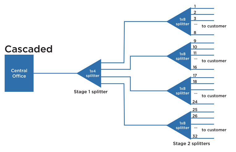
The cascaded approach may use a 1x4 splitter residing in an outside plant enclosure. This is directly connected to an OLT port in the central office. Each of the four fibers leaving this stage 1 splitter is routed to an access terminal that houses a 1x8, stage 2 splitter. In this scenario, there would be a total of 32 fibers (4x8) reaching 32 homes. It is possible to have more than two splitting stages in a cascaded system, and the overall split ratio may vary (1x16=4x4, 1x32=4x8, 1x64=4x4x4).

cascaded splitter 

Which to Choose?
 
It is important to understand both architectures in detail and weigh the trade-offs when deciding on the best approach. For most applications, the centralized approach is recommended.

First and foremost, the centralized approach maximizes the highest efficiency of expensive OLT cards. As each home in this approach is fiber-connected directly back to a central hub, there are no unused ports on the OLT card and 100% efficiency is achieved. This also allows a much wider physical distribution of the OLT ports—extremely important when initial “take rates” are projected to be low to moderate. Secondly, centralized approach is able to provide easy testing and troubleshooting access. The centralized 1x32 splitter with distribution ports enables OTDR trace development upstream to the central office and downstream to the access terminal. Also the connector ports available at the distribution hub enable qualification testing of the distribution cabling. Thirdly, loss will occur when splitters are cascaded together. The combined loss effect can reduce the distance a signal can travel, imposing distance limitations on fiber runs. The centralized splitter minimizes that signal loss by eliminating extra splices or connectors from the distribution network.

In general, the centralized architecture typically offers greater flexibility, lower operational costs and easier access for technicians, while the cascaded approach may yield a faster return-on-investment, lower first-in costs and lower fiber costs.

Summary
 
This article has reviewed some information about the split ratios and splitting level of fiber optic splitters. It is very essential to make clear all these different configurations, or the network performance will be influenced if misunderstanding or misusing the optical splitters. Hope the information in this article can help when needed.

2016年10月25日星期二

Guide for Choosing the Right Fiber Optic Cable

Fiber optic cable is a very thin glass strand through which a pulse of light is transmitted. Nowadays, fiber optic cable is a desirable cable medium due to its immunity to electromagnetic interference (EMI) and radio frequency interference (RFI). It can transport optical signals for significant distances, whether in local area, wide area, or in metropolitan area. This article will tell some information about fiber optic cables and aim at providing a guideline on choosing the right fiber optic cable.

Single-mode or Multimode Fiber Optic Cable
 
Fiber optic cable can be divided into single-mode fiber cable and multimode fiber cable. Single-mode optical fiber generally has a core diameter of 9 µm and requires laser technology for sending and receiving data. It can carry a signal for miles, which makes it ideal for telephone and cable television providers. As the name suggests, multimode fiber permits the signal to travel in multiple modes, or pathways, along the inside of the glass strand or core. It is available with fiber core diameters of 62.5 µm or 50 µm. Although the core sizes of single-mode fiber and multimode fiber differ, both fiber types end up with an outer diameter of about 250 µm. The key differences between the two kinds of fiber optic cables have been illustrated more clearly in another article—Single-mode Fiber vs. Multimode Fiber: Which to Choose?
 
Indoor Cables or Outdoor Cables
 
The major difference between indoor cables and outdoor cables is water blocking. Any conduit is someday likely to get moisture in it. Outdoor cables are designed to protect the fibers from years of exposure to moisture. Indoor cables are what we call “tight-buffered” cables, where the glass fiber has a primary coating and secondary buffer coatings that enlarge each fiber to 900 microns—about 1mm or 1/25-inch, to make fiber easier to work with.

Indoor Cables
 
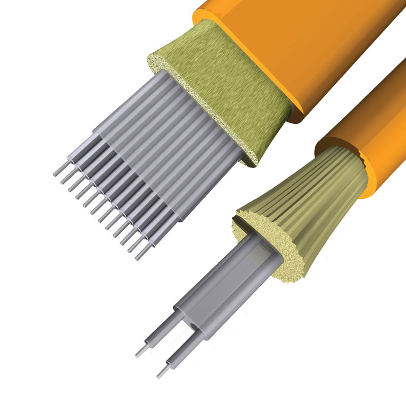
Usually, indoor cables include simplex and zipcord, distribution cables and breakout cables. Simplex fiber optic cables are one fiber, tight-buffered (coated with a 900 micron buffer over the primary buffer coating) with Kevlar (aramid fiber) strength members and jacketed for indoor use. The jacket is typically 3mm (1/8 in.) diameter. Zipcord is simply two of these jointed with a thin web. It’s used mostly for patch cord and backplane applications, but zipcord can also be used for desktop connections.

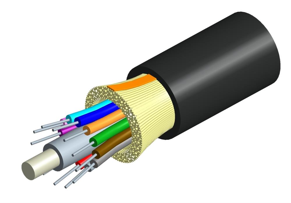
Distribution cables contain several tight-buffered fibers bundled under the same jacket with Kevlar strength members and sometimes fiberglass rob reinforcement to stiffen the cable and prevent kinking. These cables are small in size, and used for short, dry conduit runs, riser and plenum applications. The fibers are double buffered and can be directly terminated, but because their fibers are not individually reinforced, these cables need to be broken out with a “breakout box” or terminated inside a patch panel or junction box. The distribution cable is the most popular cable for indoor use.

distribution fiber optic cable 

Breakout cables are made of several simplex cables bundled together inside a common jacket for convenience in pulling and ruggedness. This is a strong, rugged design, but is larger and more expensive than the distribution cables. They are suitable for conduit runs, riser and plenum applications, and ideal for industrial applications where ruggedness is important or in a location where only one or two pieces of equipment need to be connected.

breakout fiber optic cable 

Outdoor Cables
 
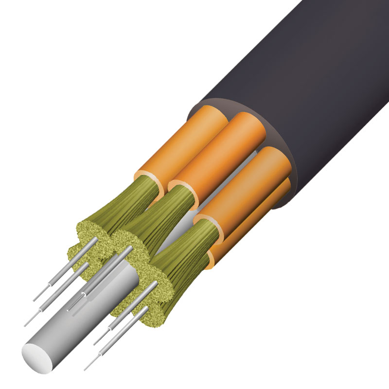
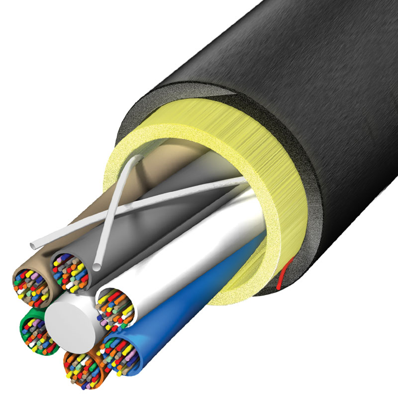
Fiber optic cables in outdoor applications require more protection from water ingress, vermin and other conditions encountered underground. Outdoor cables need increased strength for greater pulling distances. Generally, fiber optic cables installed in outdoor applications contain loose tube fiber optic cable, ribbon fiber optic cable, armored fiber optic cable and aerial fiber optic cable.

Loose tube fiber optic cables are composed of several fibers together inside a small plastic tube, which are in turn wound around a central strength member and jacketed, providing a small, high fiber count cable. They are suitable for outside plant trunking applications because they can be made with loose tubes filled with gel or water absorbent powder to prevent harm to the fibers from water. Since the fibers have only a thin buffer coating, they must be carefully handled and protected to prevent damage. They can be used in conduits, strung overhead or buried directly into the ground.

loose tube fiber optic cable 

Ribbon fiber optic cables offer the highest packing density as all the fibers are laid out in rows, typically of 12 fibers, and laid on top of each other. In this way, 144 fibers only have a cross section of about 1/4 inch or 6mm. Some cable designs use a slotted core with up to 6 of these 144 fiber ribbon assemblies for 864 fibers in one cable. Because they are outside plant cables, they are gel-filled for water blocking.

ribbon fiber optic cable 

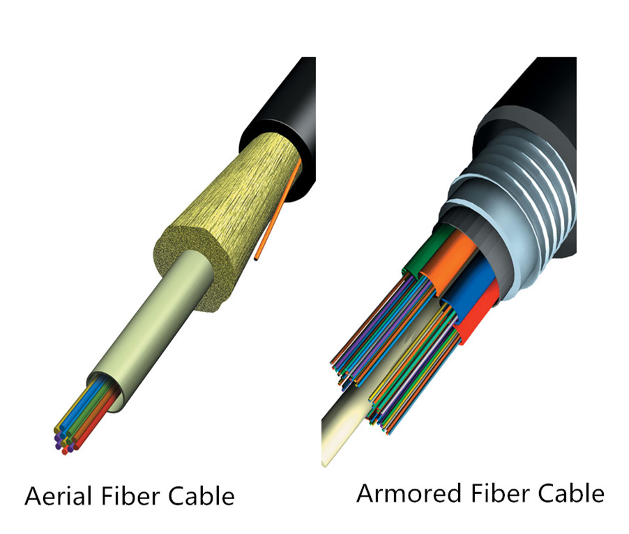
Armored fiber optic cables are installed by direct burial in areas where rodents are a problem. Usually they have metal armored between two jackets to prevent rodent penetration. This means the cable is conductive, so it must be grounded properly. It is best to choose armored fiber optic cable when use cable directly buried outdoor. Aerial fiber optic cables can be lashed to a messenger or another cable (common in CATV) or have metal or aramid strength members to make them self-supporting. Aerial cables are for outside installation on poles.

armored and aerial fiber optic cable 

Cable Jackets: PVC (OFNR), OFNP, or LSZH
 
Cable jackets can provide strength, integrity and overall protection of the fiber member. PVC is widely used as a cable jacket for many applications—computers, communications, low-voltage wiring, etc. PVC can potentially be dangerous in a fire situation, releasing heavy smoke and hydrogen chloride gas, which can be irritating to humans and corrosive to electronic devices. OFNP, or plenum jackets, are suitable for use in plenum environments such as drop-ceilings or raised floors. Many data centers and server rooms have requirements for plenum-rated cables. LSZH is a jacket made from special compounds which give off very little smoke and no toxic halogenic compounds when burned.

Summary
 
When choosing the fiber optic cables, please always remember the elements mentioned in this article. Only make clear all these aspects can you select the fiber optic cable that most suits your applications. If you are still confused about which one to choose, you can visit www.fs.com or contact sales@fs.com to seek help as lots of professional advice can be given by FS team.

2016年10月24日星期一

Traditional CWDM Mux/DeMux vs. FMU Series CWDM Mux/DeMux

With the need for bandwidth increasing, the WDM (wavelength division multiplexing) technology was developed to expand network capacity over a single fiber. It uses a multiplexer (Mux) at the transmitter to combine several signals together, and a demultiplexer (DeMux) at the receiver to split them apart. Most WDM systems operate on 9µm single-mode fiber optical cables. And they are divided into CWDM (coarse wavelength division multiplexing) and DWDM (dense wavelength division multiplexing). This article mainly focuses on CWDM system.

CWDM Mux/DeMux Overview
 
CWDM is a technology which multiplexes multiple optical carrier signals on a single optical fiber by using different wavelengths/colors of laser light to carry different signals. In a CWDM system, the CWDM Mux/DeMux is one of the most important component.

The CWDM Mux/DeMux modules are passive optical solutions which are easy to operate with a reliable low-maintenance design, and do not use power supplies or electronics. They are designed to provide optical networking support for high-speed Fibre Channel and Ethernet communication for MAN (metropolitan area network) over a grid of CWDM optical wavelengths. CWDM Mux/DeMux is capable of multiplexing and demultiplexing wavelengths up to 18 channels from 1270 nm to 1610 nm in 20nm increments. Moreover, it works seamlessly with transceivers to optimize link length, signal integrity and network cost, and can be incorporated into a single rack-mount solution for enhanced design, power and space efficiency.

Traditional CWDM Mux/DeMux System
 
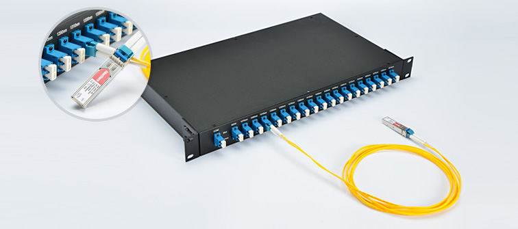
Typically, the CWDM Mux/DeMux modules interface to CWDM SFP/SFP+/XFP transceivers on an attached FC SAN or network device. This chassis-based system allows the addition of CWDM capability to any existing SAN or network device that supports LC SFP/SFP+/XFP transceivers. In short, the CWDM Mux/DeMux modules is connected with CWDM SFP/SFP+/XFP transceivers which are inserted into the switch SFP/SFP+/XFP ports by using LC single-mode patch cables.

CWDM Mux/DeMux 

The CWDM transceivers are hot-swappable, field-replaceable devices that adapt an electronic data signal to laser light at a specific wavelength. Moreover, they are color-coded to indicate the wavelength and have a color-coded clasp at one end. So the CWDM Mux/DeMux should be connected with the CWDM transceivers with the same wavelength as each transceiver will work only at the appropriate port and the data will always flow between devices with the same wavelengths. For instance, the port on the CWDM Mux/DeMux marked with 1470 nm, should be connected with the CWDM transceiver that works over 1470nm wavelength. As CWDM Mux/DeMux supports up to 18 different wavelengths, there are CWDM transceivers working over these 18 wavelengths. The following table lists the 1000BASE-CWDM SFP (20km) transceivers as an example.

Model IDWavelengthDescription
339791270 nm1000BASE-CWDM SFP 1270nm 20km DOM Transceiver
373191290 nm1000BASE-CWDM SFP 1290nm 20km DOM Transceiver
373211310 nm1000BASE-CWDM SFP 1310nm 20km DOM Transceiver
373201330 nm1000BASE-CWDM SFP 1330nm 20km DOM Transceiver
526741350 nm1000BASE-CWDM SFP 1350nm 20km DOM Transceiver
526751370 nm1000BASE-CWDM SFP 1370nm 20km DOM Transceiver
526761390 nm1000BASE-CWDM SFP 1390nm 20km DOM Transceiver
526771410 nm1000BASE-CWDM SFP 1410nm 20km DOM Transceiver
526781430 nm1000BASE-CWDM SFP 1430nm 20km DOM Transceiver
526791450 nm1000BASE-CWDM SFP 1450nm 20km DOM Transceiver
526801470 nm1000BASE-CWDM SFP 1470nm 20km DOM Transceiver
526811490 nm1000BASE-CWDM SFP 1490nm 20km DOM Transceiver
526821510 nm1000BASE-CWDM SFP 1510nm 20km DOM Transceiver
526831530 nm1000BASE-CWDM SFP 1530nm 20km DOM Transceiver
526841550 nm1000BASE-CWDM SFP 1550nm 20km DOM Transceiver
526851570 nm1000BASE-CWDM SFP 1570nm 20km DOM Transceiver
526861590 nm1000BASE-CWDM SFP 1590nm 20km DOM Transceiver
526871610 nm1000BASE-CWDM SFP 1610nm 20km DOM Transceiver

FMU Series CWDM Mux/DeMux System
 
FMU CWDM Mux/DeMux modules are new types of modules launched by FS.COM. Compared with the traditional CWDM Mux/DeMux modules, the new FMU series modules are more user-friendly and show completely new characteristics.

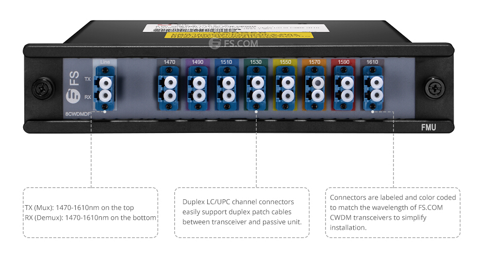
With low-profile modular design, the FMU CWDM Mux/DeMux modules plug into one half of a 1RU, 19” rack mount chassis for simple installation and modularity. This chassis based system allows a network equipment manufacture to add CWDM capability to any existing networks with simple pluggable interface. Besides, the equipment ports of the FMU CWDM Mux/DeMux modules are color-coded to match the wavelengths of CWDM transceivers to simplify installation and troubleshooting without having to remove the transceivers from the local equipment. This color-coded feature is the major advantage of this new FMU series modules and it do greatly simplify the process of connecting a CWDM transceiver to its associated device port. The following picture is an example of 8 channels 1470-1610nm dual fiber CWDM Mux/DeMux. This new FMU series CWDM Mux/DeMux modules deliver dramatic cost savings to network equipment manufacturers, enabling them to develop metro access systems that are lower in cost, easier to provision and simpler to operate.

8 channels 1470-1610nm dual fiber CWDM Mux/DeMux 

The following table lists FS.COM FMU series CWDM Mux/DeMux modules.

Model IDDescription
435544 channels 1470-1590nm single fiber CWDM Mux Demux
435534 channels 1490-1610nm single fiber CWDM Mux Demux
429724 channels 1270-1330nm dual fiber CWDM Mux Demux
429444 channels 1510-1570nm dual fiber CWDM Mux Demux
437808 channels 1290-1590nm single fiber CWDM Mux Demux
437798 channels 1310-1610nm single fiber CWDM Mux Demux
429458 channels 1290-1430nm dual fiber CWDM Mux Demux
430978 channels 1470-1610nm dual fiber CWDM Mux Demux
437119 channels 1270-1590nm single fiber CWDM Mux Demux
436999 channels 1290-1610nm single fiber CWDM Mux Demux
483934 channels 1470-1590nm single fiber CWDM Mux Demux with expansion port
483944 channels 1490-1610nm single fiber CWDM Mux Demux with expansion port
429734 channels 1510-1570nm dual fiber CWDM Mux Demux with expansion port
430998 channels 1470-1610nm dual fiber CWDM Mux Demux with expansion port
3348918 channels 1270-1610nm dual fiber CWDM Mux Demux with monitor port
304081RU Rack Mount Chassis unloaded, holds up to 2 units half 19''/1RU FMU Cassettes

Note: The modules with expansion port allows adding or expanding more CWDM wavelengths/channels to the network for future upgrade. If used, it will be treated just like the other ports and up-jacketed and terminated as needed. If not used, it will be cut back into the module and terminated in a way to reduce reflections.

Conclusion
 
Both the traditional CWDM Mux/DeMux and the FMU series CWDM Mux/DeMux are used to increase fiber network capacity without the expense of deploying more fiber cables. They make full use of the low loss bandwidth of optical fiber to achieve ultra high bit rate transmission. The key difference is that it is more convenient and efficient for the FMU CWDM Mux/DeMux to connect with the CWDM transceivers. FS.COM provides both the two kinds of CWDM Mux/DeMux modules. For more details, you can visit www.fs.com.

2016年10月14日星期五

Guide for Choosing the Suitable Ethernet Cables

Not all Ethernet cables are created equally. They are grouped into sequentially numbered categories (“cat”) based on different specifications. Generally, there are Cat 5e, Cat 6, Cat 6a, Cat 7 cables, etc. What are the differences between these different kinds of Ethernet cables? And how to choose the suitable one for your network? This article will provide some information about what should be considered when choosing.

Characteristics of Different Cables
Before choosing the Ethernet cables, we should first know the characteristics of each kind of Ethernet cable.

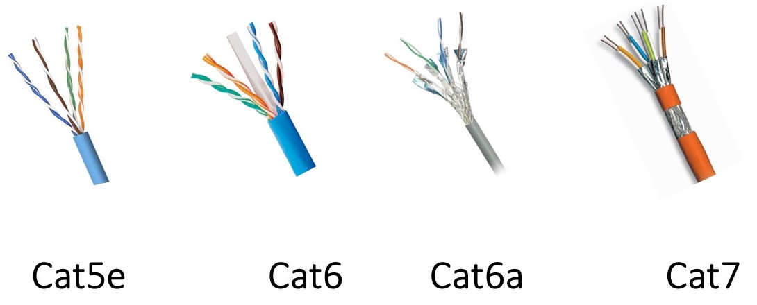
cat 5e, cat6, cat7 

Cat 5 cables are designed to support theoretical speed of between 10 Mbps and 100 Mbps. However, gigabit speeds can still be attained with Cat 5 cable particularly if the cable is shorter, but is not always a guarantee. It supports a bandwidth of up to 100 MHz. The “e” in Cat 5e stands for “enhanced” and as the name suggests, it is basically an improvement on Cat 5 cables. In theory, it should be ten times faster than the Cat 5 cables without a substantial price increase. It supports up to 1000 Mbps or gigabit speeds. The Cat 5e cables have lower crosstalk and provide a faster, reliable and steady speed than Cat 5 cable.

Cat 6 cables have more stringent specifications than Cat 5e cables and are capable of supporting 10 Gbps. They have slighter thicker wires, and the cores are more tightly twisted together. This means the cables are thicker and less flexible than Cat 5e cables. The Cat 6 cables are recommended for large organizations which deal with pretty bulk files. For home purposes, Cat 5 and Cat 5e are positively enough. Cat 6a cables have improved properties and can operate at 500 MHz and can support 10 Gbps to a maximum distance of 328 feet. It should be noted that cable termination requirements for Cat 6 and Cat 6a cables are stringent, and the cables require better protection than Cat 5e cables.

Cat 7 cables feature even more strict specifications for crosstalk and system noise than Cat 6. And shielding have been added for individual wire pairs on the Cat 7 cables. They have been designed for Gigabit Ethernet over 100 m of copper cabling, and they are rated for transmission frequencies of up to 600 MHz. Cat 7a cables operate at frequencies up to 1000 Mhz. They are designed for multiple applications in a single cable including 40G, 100G and CATV. The transmission distance can be up to 50 m for 40G, and 15 m for 100G.

Factors to Consider
Following lists two factors that should be considered when choosing the cables, which are STP/UTP cables and solid/stranded cables.

STP or UTP
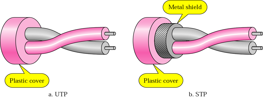
STP (shielded twisted pair) cables simply have additional shielding material that is used to cancel any external interference that may be introduced at any point in the path of the cable. UTP (unshielded twisted pair) cables have no protection against such interference and its performance is often degraded in its presence. But both of them have interference canceling capacities.

UTP, STP 

Typically, using STP cables ensures that you can get the maximum bandwidth from your cabling even if the external condition is less than ideal. STP cables work by attracting interference to the shield, then running it off into a grounded cable. If the cable is improperly grounded, then its noise-canceling capabilities are severely compromised. Additionally, STP cables have bigger diameter than UTP cables, and they are more expensive. Besides, they are more fragile as the shield must be kept intact to ensure them work properly. STP cables are commonly used in industrial settings with high amounts of electromagnetic interference, such as a factory with large electronic equipment, where they can be properly installed and maintained. They can also be used in outdoor environments where the cables are exposed to the elements and man-made structures and equipment that may introduce additional interference.

UTP cables are smaller than STP cables, which makes them easier to install, particularly in bulk or in narrow spaces. They do not require the presence of a grounding cable and do not require much maintenance, but transmit data as fast as STP cables. Generally, UTP cables are more prone to noise than properly installed and maintained STP cables. They are more prevalent and popular used in domestic and office Ethernet connections, and in any area where there is not a high degree of electromagnetic interference.

Solid or Stranded
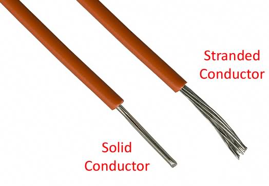
Both solid and stranded Ethernet cables refer to the actual copper conductor in the pairs. The solid cable uses one solid wire per conductor, so in a standard Cat 5e or Cat 6 four pair (8 conductor) roll, there would be a total of 8 solid wires. Stranded cable uses multiple wires wrapped around each other in each conductor, so in a 4 pair (8 conductor) 7 strand roll (typical configuration), there would be a total of 56 wires.

solid cable, stranded cable 

Solid cables are most useful for structured wiring within a building. They can be easily punched down onto wall jacks and patch panels as they have only one conductor. The wire seats properly into insulation displacement connector. Solid cables are less useful when you are terminating with standard RJ45 connectors, as used when making patch cables. Most RJ45 connectors use 2 prongs which penetrate the conductor itself. This is not desirable, since solid cable has the tendency to break when penetrated by the prong. Using a 3 prong style RJ45 connectors creates a much better connection as it doesn’t break the conductor—the 3 prongs style connection wraps around the conductor instead of penetrating it. It is recommended that stranded network cable be used for patch cables as they make better quality RJ45 termination connections than even using 3 prong connectors.

Stranded cables are much less useful for punching down on wall jacks because the strands do not keep their perfect round shape when thrust into a insulation displacement connector. For best results, use solid for wall jacks and stranded for crimp connectors. Stranded cable is typically used to create patch cables. The cable itself is more flexible, and rolls up well. The RJ45 terminators have a better, and more flexible and complete connection to stranded wires than solid wire.

Summary
Be sure to make clear of every kind of Ethernet cables and take each of the factors above into account before finally selecting the one for your home or business project. Hope the information in this article could be helpful or a guide for you when you are confused about which Ethernet cable to choose.

2016年10月5日星期三

How to Get Proper Cable Management in Data Center?

Data center is the heart that pumps the lifeblood of your business. Without it, everything stops. And when there is anything wrong in the data center, so does your business. For many data centers, managing cables is an afterthought. But actually, cable management is one of the most important aspects of data center design. Following cable management tips are helpful in the day-to-day facility management of a data center.

Measure Twice, Cut Once
It’s an old adage, but an important one. If you don’t carefully measure your cables, not only you create a tangled mess, but also you create a lot of expensive waste. You may think that two feet of wasted cables does not amount much, but when add up those wasted feet, it would be a huge cost. So please remember to measure twice while cut once to save yourself a lot of time and money.

Cable Labeling
Be it a power or data cable, labeling cables can prove to be critical if a problem arises. Cable labels should be secured in a way that will make them accessible, yet difficult to remove. If you don’t label your cables, you are only making more work for yourself. Imagine you have to test a bunch of circuits quickly. You scramble and unplug a few patch cables, and when it’s time to reset them back to their default locations, you have no idea where each cable goes. Avoid this problem by taking a little time to slap a cable label on each end.

cable label
Cable Testing
All cables should be pre-tested prior to installation. Once installed, it is much harder to test and identify problems. If a test doesn’t pass 100%, redo that cable. After a few tries at termination, if the cable still doesn’t pass, trash it. And make sure you’re using a quality tester for your cables and you know precisely how to use it. This simple step can prevent a lot of extra work in the end.

Run Cables in Hot Aisle
Proper airflow in and around the data center is critical to optimal operating efficiency. Keep underfloor power cables in the hot aisle running parallel to the computer room air conditioner (CRAC) unit’s airflow. Consider elevating mounting positions for the receptacles to help protect against possible pooling water and cable air dams, allowing for better air flow and improved CRAC unit efficiency. Running data cables only in the hot aisle, organizing cables using horizontal and vertical cable managers will help to improve airflow through the racks, avoiding hot spots and possible outages.

Cable Ties
Use cable ties to hold groups of data cables together or to secure cables to components. Velcro cable ties are versatile and can be reused or adjusted as cables are added or moved. If you use zip ties, make sure clipped ends of the ties are disposed properly and don’t end up a contaminant in the plenum cooling system.

cable tie
Color Code
Color provides quick visual identification. Color coding simplifies management and can save you time when you need to trace cables. With data cables, use color to identify their role/function of the cables or the type of connection. With power cables, use different colors to identify and organize dual power feeds for redundant power sources.

Cable Managers
Choose the best cable managers for your application. No one cable manager can be universally used. Some cable managers are simple and use hooks to organize cabling bundles. Others are more complex and allow individual cable runs to exit at various points. Some of these more elaborate cable managers have covers to hide bundles and keep your installation neat.

cable manager
Summary
This article have introduced several tips for improved cable management. It is a simple and inexpensive cable management solution to keep your data center cables organized according to predetermined scheme and routed in specified locations. Hope the cable management tips mentioned above can do you a favor in your data center cable managing.

2016年9月24日星期六

FBT Splitters vs. PLC Splitters: What Are the Differences?

Fiber optic splitters play an increasingly significant role in many of today’s optical network topologies. They provide capabilities that help users maximize the functionality of optical network circuits from FTTx systems to traditional optical networks. And usually they are placed in the central office or in one of the distribution points (outdoor or indoor). This article will tell something about optical splitters.

What Is Fiber Optic Splitter?
 
A fiber optic splitter is a passive optical device that can split or separate an incident light beam into two or more light beams. These beams may or may not have the same optical power as the original beam, based on the configuration of the splitter. By means of construction, the outputs of a splitter can have varying degrees of throughput, which is highly beneficial when designing optical networks, whether the splitter is used for network monitoring or for a loss budget in a passive optical network (PON) architecture. Generally, there are two types of fiber optic splitters, which are FBT (fused biconical taper) splitters and PLC (planar lightwave circuit) splitters.

fiber opitc splitter
 
FBT Splitters
 
FBT is the traditional technology in which two fibers are placed closely together, typically twisted around each other and fused together by applying heat while the assembly is being elongated and tapered. A signal source controls the desired coupling ratio. The fused fibers are protected by a glass substrate and then protected by a stainless steel tube, typically 3 mm diameter by 54 mm long. FBT splitters are widely accepted and used in passive optical networks. The following picture shows a 1×2 FBT splitter single-mode three window fiber splitter with ABS box.

FBT splitter
 
PLC Splitters
 
The PLC splitters are used to separate or combine optical signals. A PLC is a micro-optical component based on planar lightwave circuit technology and provides a low cost light distribution solution with small form factor and high reliability. PLCs are manufactured using silica glass waveguide circuits that are aligned with a v-groove fiber array chip that uses ribbon fiber. Once everything is aligned and bonded, it is then packaged inside a miniature housing. PLC splitters have high quality performance, such as low insertion loss, low PDL, high return loss, etc. The following is a picture of 1×8 blockless PLC splitter.

PLC splitter
 
Comparison Between FBT Splitters and PLC Splitters
 
The differences between FBT splitters and PLC splitters are described in the following table.

FBT vs. PLC 

In a word, the FBT splitters have lower costs but restricted to the operating wavelength, and the maximum insertion loss will vary depending on the split and increase substantially for those splits over 1:8. While the PLC splitters, with higher costs, have equal splitter ratios for all branches as well as low failure rate.

FS.COM Fiber Optic Splitters Solution
 
As a leading supplier in fiber optic communication industry, FS.COM provides various kinds of PLC splitters and FBT splitters. Moreover, our fiber optic splitter quality and performance is not only guaranteed by using high-quality components and stringent manufacturing processes and equipment, but also by adherence to a successful quality assurance program, which can be checked in “FS.COM Quality Assurance Program for PLC Splitter”. For more details, you can visit www.fs.com.

2016年9月20日星期二

Basis of Pre-terminated Trunk Cable Assemblies

Pre-terminated trunk cable assemblies provide an ideal plug-and-play solution for links between switches, servers, patch panels, and zone distribution areas in the data center. Compared with field-terminated cabling, the pre-terminated cable assemblies can accelerate the process, reduce costs and errors, and can help bring your data center online in less time. This article will tell something about pre-terminated cabling.

What Can Pre-terminated Trunk Cables Achieve?
 
There are many benefits of deploying pre-terminated cable assemblies.
  • Increase Speed of Deployment
Field termination is the most time-consuming, labor-intensive part of the cable installation process. Once pre-terminated cable assemblies are delivered, they are ready for deployment, and can be connected quickly. In many cases, pre-terminated cables can cut installation time by up to 80% over field terminations.
  • No Need for Performance Testing
The transmission testing of pre-terminated cable assemblies is performed by the manufacturer before shipment, and test reports are included with the assemblies. This leaves only continuity testing for copper and 10% insertion loss and continuity testing for fiber, which reduces the time spent testing on-site.
  • Reduce Downtime With Faster, More Flexible MACs
With pre-terminated solutions, data center managers can make changes quickly based on network growth, business decisions, or shifting requirements. In disaster recovery situations that call for fast, temporary data communications set-up, pre-terminated cabling can minimize business downtime and establish communications quickly. It can be disassembled quickly when the situation is resolved. The components are reusable for more efficient moves, adds, and changes (MACs).
  • Cut Clean-up Time
Pre-terminated solutions allow for quick clean-up due to minimal leftover materials and scrap. Also, because there is less waste material to clean up, pre-terminated solutions also help meet green design, waste reduction, and material reuse goals.

Common Types of Pre-terminated Trunk Cables
 
There are pre-terminated fiber cabling and pre-terminated copper cabling. This part will introduce two kinds of commonly used pre-terminated trunk cable assemblies: pre-terminated fiber trunk cable, and pre-terminated copper trunk cable.
  • MTP/MPO Trunk Cables
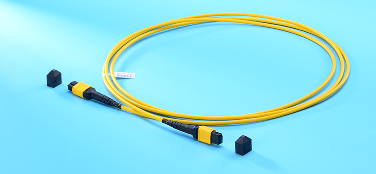
Pre-terminated with MTP/MPO connectors on both ends, the MTP/MPO trunk cables provide a quick-to-deploy, scalable solution that improves reliability and reduces installation time and cost. They are capable of supporting multiple users or devices from one point to another while distributing multiple data channels, which is a convenient and economical alternative to running multiple jumpers or patch cables. Generally 12-fiber MTP/MPO trunk cables and 24-fiber MTP/MPO trunk cables are commonly used separately for 40G applications and 100G applications. The following picture is a 12-fiber female to female MTP single-mode trunk cable.

MTP/MPO trunk cable 

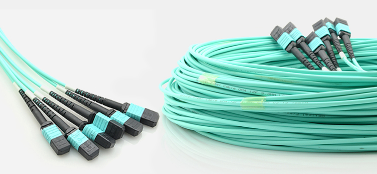
There are also high fiber count MTP/MPO trunk cables which have several legs on both ends. The following picture shows a 72-fiber MTP/MPO trunk cable. There are 6 legs on both ends with each leg terminated with a 12-fiber MTP/MPO connectors.

MTP/MPO trunk cable
  • Pre-terminated Copper Trunk Cables
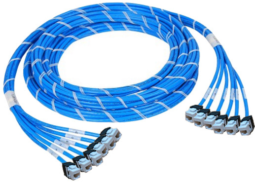
The pre-terminated copper trunk cable is a bundle of category cables, built with a choice of 6, 12, or 24 cable bundle and factory terminated with jacks and plugs. They allow fast and easy installation with reduced labor costs in large copper infrastructures with high-density cross-connection and patching systems. The pre-terminated copper cable assemblies offered by FS.COM are pre-bundled and pre-labeled styles, available in Cat 5e, Cat 6 and Cat 6a UTP and STP cable constructions with each available in jack to jack, plug to plug and jack to plug termination ends.
pre-terminated copper trunk cable 

How to Choose the Suitable Pre-terminated Trunk Cables?
 
When selecting pre-terminated cable assemblies, the following tips are for your reference.
  • Be sure to use a reliable vendor that can offer services such as guaranteed cabling performance, design assistance, certified contractor training, and the ability to support large quantities of assemblies in the required delivery window.
  • Make sure the pre-terminated fiber or copper cabling purchased through a manufacturer uses components that have been tested and verified by a third party to exceed TIA and IEEE standards. The manufacturer should also provide 100% testing in a quality-controlled environment before the cabling is shipped out to the work site.
Summary
 
Pre-terminated trunk cable assemblies are perfect for data centers and other applications where speed and testing simplify installation. They help to save time, and labor. FS.COM provides various kinds of high-quality but low-price pre-terminated cable assemblies. And all of them are tested before shipment. If you need, please visit www.fs.com.