2017年3月27日星期一

How to Run Cables in Multi-Floor Data Center With Fiber Enclosures?

In the previous post—Modular Patching Solutions for Flexible Cable Management, I have introduced one kind of FHD fiber enclosure with user-friendly slide-out drawer and flexible mounting options. Actually, besides that rack mount fiber enclosure, there is another kind of FHD fiber enclosure useful in cable running and managing: wall mount fiber enclosure. It is very convenient for multi-floor cabling. This post will tell how to run cables in multi-floor data center by flexible usage of fiber enclosures.

Fiber Enclosure – One Key Component for Cable Routing and Managing
 
Both wall mount fiber enclosure and rack mount fiber enclosure can be used in the multi-floor data center. Here I only say something about wall mount fiber enclosure as rack mount ones have been introduced in the previous post.
wall mount fiber enclosures 

Figure 1: Wall mount fiber enclosures with two mounting options

As the name shows, wall mount fiber enclosures are usually installed on the wall for cable routing and managing. Take FS.COM wall mount fiber enclosure for example, the wall mount fiber enclosures can be loaded with 2, 4, 8 fiber adapter panels and 2 slack spools for easy-to-manage environment for fiber patch cables, or 2, 4, 8 MTP cassettes for maximum density in limited spaces while reducing installation time.

User Case Scenario Analysis
 
Usually there are racks and racks or cabinets and cabinets in the data center. Proper cable connecting among the racks is vital to future cable moves, adds and changes. Generally, fiber enclosures are a good way and used to route and manage fiber cables. This part will show one user case scenario to tell how to run cables in multi-floor data center. The following picture demonstrates the situation.
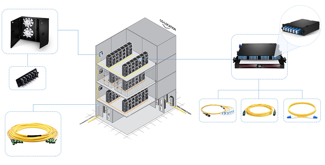
multi-floor deployment scenario with fiber enclosures 

Figure 2: Multi-floor data center cable routing scenario

In this case, the wall mount fiber enclosures loaded with MTP fiber adapter panel and the rack mount fiber enclosure loaded with MTP cassette are used to manage the fiber cables. The MPO fiber cables can be used to provide backbone interconnection between data center distribution zone areas and provide patching for parallel transceiver or array equipment. There are standard 12f and 24f MPO trunk cables as well as 48f MPO trunk cable and 72f MPO trunk cable. MTP cassettes installed inside the fiber enclosure can be used to connect the front LC fiber jumpers to the back MPO fiber cables. Or the MTP cassettes can be replaced with MTP fiber adapter panel for direct trunk cable to fan out interface. No matter how you run your data center cabling, fiber enclosures are undoubtedly important for routing and managing the fiber cables with flexible MACs—wall mount fiber enclosure for cable connecting between floor and floor while rack mount fiber enclosure for cabling connecting between or within racks and racks.

What Can We Summarize?
 
Using MTP/MPO cassettes, MPO fiber cables, and fiber enclosures are smart way to deploy your network neatly, conveniently and flexibly. They can build a complete easy-to-manage system in the multi-floor data center. Deploying the fiber enclosures and MPO fiber cables at first for good management will do better than re-routing and re-configuring the cabling at last. Do you think so? If “Yes”, buy the MTP cassettes, fiber enclosures and MPO fiber cables from FS.COM with the most competitive price! More details, visit www.fs.com.

2017年3月20日星期一

Modular Patching Solutions for Flexible Cable Management

As is known to all, data center cable management is not that easy. If the cables are not managed well at first, managing the cables will be a nightmare at last. So how to quickly and effectively manage your data center cabling in the beginning would become particularly important. Modular patching solutions are practical ways for great capacity cabling management. Fiber enclosure, MTP cassette and fiber adapter panel play important roles in the modular patching solution. This post will talk about cable management with modular patching solutions.

Key Components: Fiber Adapter Panel, MTP Cassette, FHD Fiber Enclosure
 
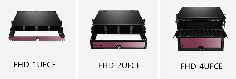
Preloaded with fiber adapters, the fiber adapter panels serve as the intermediate connection between the backbone and the patching cabling. The commonly used fiber adapter panels are LC fiber adapter panels, SC fiber adapter panels and MTP/MPO fiber adapter panels. In the previous post “Type A MTP Cassette and Type B MTP Cassette: When and Where to Use?”, I have talked a lot about MTP cassette. So here I’m not going to talk about it in detail. As for the fiber enclosures, take FS.COM fiber enclosures (FHD-1UFCE, FHD-2UFCE, FHD-4UFCE) for example, these three types of FHD fiber enclosures are with the size of 1RU, 2RU and 4RU respectively. Made of black powder coated SPCC rugged heavy-duty steel, the FHD fiber enclosures are designed with push/pull out functions, and have flexible mounting options, which are suitable for 10G/40G/100G cabling deployment.

FHD fiber enclosure: FHD-1UFCE, FHD-2UFCE, FHD-4UFCE 

Solution 1: MTP Cassette With FHD Fiber Enclosure
 
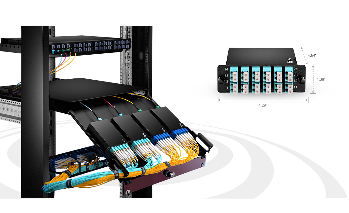
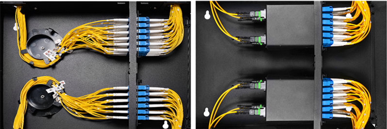
FHD-1UFCE fiber enclosure can hold up to four MTP/MPO cassettes, FHD-2UFCE fiber enclosure eight MTP/MPO cassettes, and FHD-4UFCE fiber enclosure twelve MTP/MPO cassettes. Matching with 24-fiber MTP LC cassette, the maximum fiber counts of these three FHD fiber enclosures are 96 fibers, 192 fibers and 288 fibers. Can you imagine how much valuable space they can save for you in the data center? The following picture demonstrates the well organized cabling in modular system.

MTP Cassette With FHD Fiber Enclosure 


Solution 2: Fiber Adapter Panel With FHD Fiber Enclosure
 
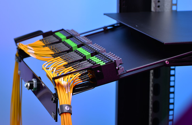
In addition to housing MTP/MPO cassettes, those three FHD fiber enclosures can also hold the fiber adapter panels. When holding adapter panels, there are some differences with holding MTP/MPO cassettes. Besides housing the exact same number of fiber adapter panels, the FHD-1UFCE fiber enclosure can also hold two fiber slack management spools or four optical splice trays. And FHD-2UFCE fiber enclosure can hold two fiber slack management spools or eight optical splice trays, while FHD-4UFCE fiber enclosure can hold two fiber slack management spools or twelve optical splice trays. If choosing to use fiber slack management spools, they can help to manage the cables. If choosing to use the optical splice tray, they can help to store the spliced fiber pigtails.

Fiber Adapter Panel With FHD Fiber Enclosure 

Two Patching Solutions: When to Use Each?
 
Both the two fiber patching solutions talked above would definitely save your data center space or installation time. Which solution to use depends on your special network deployments. If you need to connect your backbone MTP cabling with the standard patch cables, using the MTP/MPO cassette with fiber enclosure would be a good choice. If simply connecting the fiber patch cables, using the fiber adapter panels with fiber enclosure would be more suitable. No matter which solution to use, undoubtedly they provide high density flexible system for managing fiber terminations, connections and patching in data center application to maximize rack space utilization and minimize floor space.

Note: If using FHD fiber enclosure with MTP/MPO cassette, fiber slack management spools or optical splice trays cannot be installed inside the enclosure.

2017年3月15日星期三

Type A MTP Cassette and Type B MTP Cassette: When and Where to Use?

Modular system, which allows for rapid deployment of high density data center infrastructure and improved troubleshooting and reconfiguration during MACs, is more and more popular. MTP cassette, topic of this post, is such a module. It provides a secure transition between MTP and LC or SC discreet connectors, and is used to interconnect MTP backbone cabling with LC or SC patch cables.

MTP Cassette Appearance
MTP fiber optic cassettes are pre-terminated and pre-tested enclosed units. They contain 12-fiber or 24-fiber factory terminated fan-outs inside. MTP modular cassettes serve to “transition” small diameter ribbon cables terminated with MPO connector(s) to the more common LC or SC interface used on the transceiver terminal equipment. Typically, the fan-outs incorporate LC, SC connectors plugged into adapters on the front side of the cassette and MPO connector(s) plugged into MPO adapter(s) mounted at the rear of the cassette. One or more MPO fan-out assemblies can be installed inside the cassette to connect up to two 12-fiber ribbon cables for a total of 24 fibers. Alignment pins are pre-installed in the MPO connector located inside the cassette. These pins precisely align the mating fibers in the MPO connectors at either end of the array cables that plug into the cassettes.

12-fiber MTP LC cassette and 24 fiber MTP LC cassette

MTP Cassette Polarity: Method A or Method B
The transition inside a MTP cassette, the connector keying for the MTP cassette module and the corresponding MPO array cables are completely defined for all three connectivity methods listed in the TIA standard as described in the previous post—polarity methods for MTP/MPO system. A common transition, factory installed inside a cassette, is used for all of the three methods. The adapter mounted at the rear of a cassette defines it as either Method A or Method B MTP modular cassette.

Method A MTP Cassette vs. Method B MTP Cassette
Method A MTP cassette makes a “key up to key down” connection between the internal MPO connector and the MPO array cable connector. Method B MTP cassette makes a “key up to key up” connection. The Method B cassette will not allow single-mode angle polish mated pair connections due to the fact that the angles of the mating connectors are not complementary. This prevents a Method B MTP cassette module or adapter from being used in single-mode applications requiring low return losses, a significant limitation with connectivity Method B. The difference between Method A and Method B MTP fiber optic cassette is the orientation of the internal MPO connector with respect to the mating with MPO array cable connector.

Connectivity Rules of Method A and Method B MTP Cassette
The components deployed for multiple duplex signals include a MTP cassette at each end. Pre-terminated 12-fiber trunk cables connect to the MPO adapter on the back of the two cassettes, and duplex patch cords are used to connect the equipment to the front of the cassettes. There are two types of patch cords “A-to-B” and “A-to-A” and three types of trunk cables “Type A”, “Type B”, “Type C” shown in the following pictures.

duplex patch cord
Type A MTP trunk cable, Type B MTP trunk cable, Type C MTP trunk cable

The following picture clearly shows the connection rules of every component required for the three connectivity methods.

polarity methods for Method A, Method B, Method C
From the picture, we can summarize following connection points:
  • Connectivity Method A is the most straight forward but requires a different patch cord at one end.
  • Connectivity Method B uses the same patch cord at both ends, but the cassettes (circled in red) must be flipped over at one end so that the fiber that originated in position 1 is mapped to position 12.
  • Connectivity Method C is a variant of Method A, but with the cross-over implemented in the trunk cable instead of the patch cord.
Note: No matter which method is selected, there must be a pair-wise flipping (A-to-B polarity swap) that takes place at some point in the link. If the pair-wise flipping does not occur in the cassette then the pair-wise flipping must occur in the duplex patch cord or the MPO trunk cable and/or adapters.

The following picture shows an illustration of the connectivity rules. The numbers shown next to the adapters on the outside of the cassette and the MPO connectors are fiber port designations. The numbers shown in bold next to the adapters on the inside of the cassette are fiber number designations.

illustration for Method A, Method B and Method C 

Summary
MTP cassette, containing factory controlled and tested MPO/MTP-LC fanouts, delivers high optical performance, rapid and error-free installation and reliable robust operation. Using Type A MTP cassette or Type B MTP cassette is closely related to the other components in the whole system. The best way to maintain correct optical polarity is to choose a standards-based approach and adhere to it throughout an installation. Incorrect connections violating the proper polarity will result in a link failure and possibly damage to critical optoelectronic components. It is best for installers and end-users to buy MTP cassette from a supplier adhering to TIA standards. FS.COM is such a MTP cassette modules manufacturer, who provides both 12 core and 24 core MTP/MPO fiber optic plug-n-play cassettes with low price.

2017年3月9日星期四

MTP-8 Solution: Future-Proof Connectivity in Data Center

In most data centers, MTP cable is widely used for high density application. MTP-12 connectivity and MTP-24 connectivity are the two common types of cabling connections, which use links based on increments of 12 and 24, such as 12-fiber trunk cables and 24-fiber trunk cables. In addition to MTP-12 and MTP-24, there is another MTP solution—MTP-8. In a MTP-8 solution or Base-8 solution, 8-fiber trunk cables, 24-fiber or 32-fiber trunk cables can be used to transmit data. In brief, MTP-8 solutions use cable links based on increments of the number “eight”. This post will explain the benefits of MTP-8 solution and show its application in 10G/40G data centers.

Why MTP-8 Appears?
 
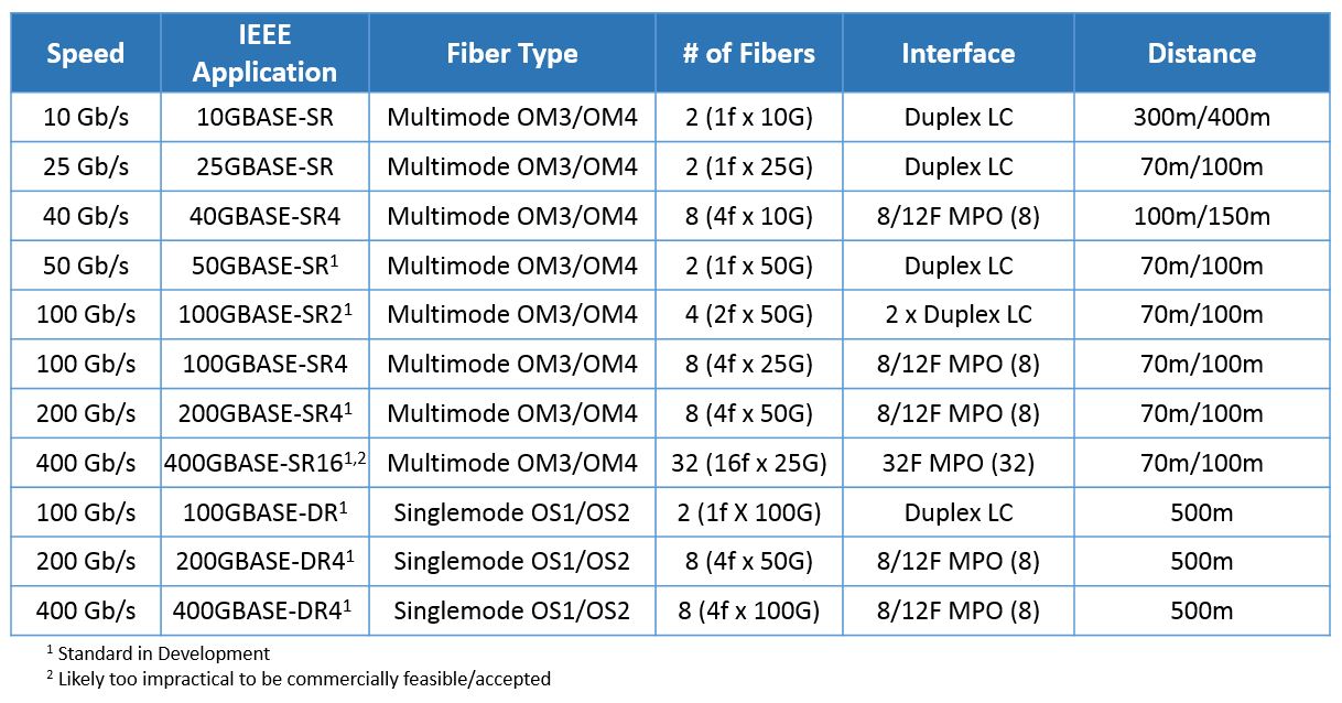
With MTP-12 and MTP-24 using in the data center for years, you may ask why there is still a need for MTP-8? In fiber optic industry, optical transceiver roadmap changes rapidly from 10G—40G—100G and even up to 400G (see the picture below). With faster speeds spreading out into data center racks and SANs, there is a need for a more manageable grouping. For 40G connections and above, data is usually carried over eight fibers, and terminated at the switch in a MTP-8 QSFP transceiver which combines eight fibers.

40G/100G/400G use MTP-8 solution 

From the picture, we can see that for Ethernet transmission ranging from 40G to 400G, all roads lead to 2-fiber and 8-fiber solution. For 40G/100G and future 400G applications, the use of 12-fiber MTP solution would result in 33% of the optical fibers unused. Thus it is expected that for 400G application, MTP-8 will gain widespread market acceptance.

MTP-8 Solution Benefits
 
Flexibility and 100% fiber utilization are the primary advantages of MTP-8 solution. Being wholly divisible by number “2”, MTP-8 solution can be easily used for two-fiber transceiver systems, just as MTP-12 solution can be. And for those who have deployed 12-fiber or 24-fiber trunk cables, how to ensure the 100% fiber utilization? MTP-8 can. You can use conversion cords or modules to transition two 12-fiber or one 24-fiber trunk from backbone cabling into three 8-fiber MTP for 40G/100G equipment connection. But in this process, conversion modules will introduce additional insertion loss into the channel and conversion cords. Thus deploying MTP-8 solution directly can ensure 100% fiber utilization without the additional cost and insertion loss of MTP-12 to MTP-8 conversion devices. In a word, for the most common 40G/100G/400G transceiver types, MTP-8 solution offers the most flexibility and uses the fibers to the fullest.

MTP-8 Solution in Data Center
 
As stated above, MTP-8 solution can be used in different applications. Here I’d like to show three examples.

Example 1: MTP trunk cable in 40G 
 
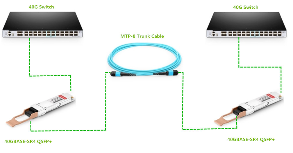
In 40G data center, the simplest way to connect two 40G switches is to use the MTP trunk cable. As the picture shows, 40G data transmission can be achieved by connecting the both ends of the MTP trunk cable with the 40G QSFP transceivers inserted into the two 40G switches.

MTP-8 solution in 40G data center 

Example 2: MTP to LC breakout cable in 10G/40G
 
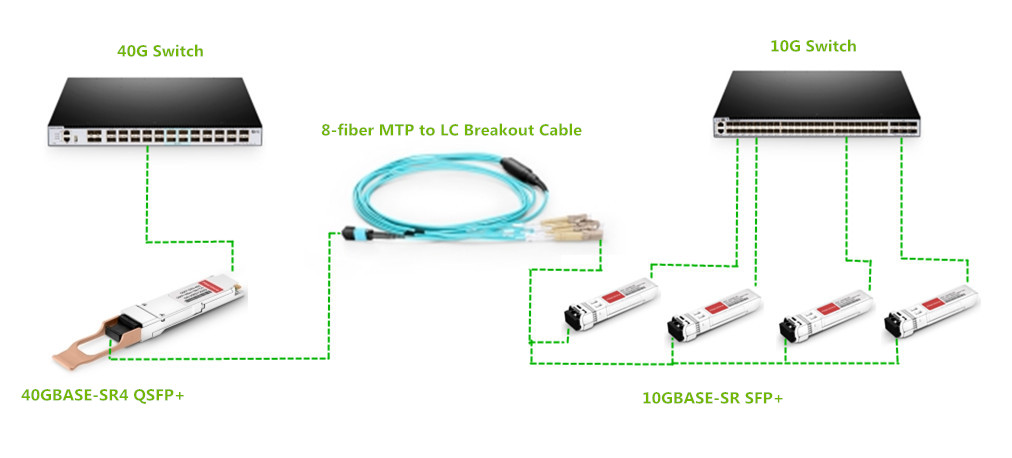
For 10G to 40G migration, using the MTP breakout cable is a simple way. As shown in the following picture, the MTP to LC breakout cable connects a 40G transceiver and four 10G transceivers. So the 40G data can be transmitted from 10G switch to 40G switch through the MTP to LC breakout cable.

8 fiber MTP-LC breakout cable in 10G/40G migration 

Example 3: MTP LC patch panel in 10G/40G
 
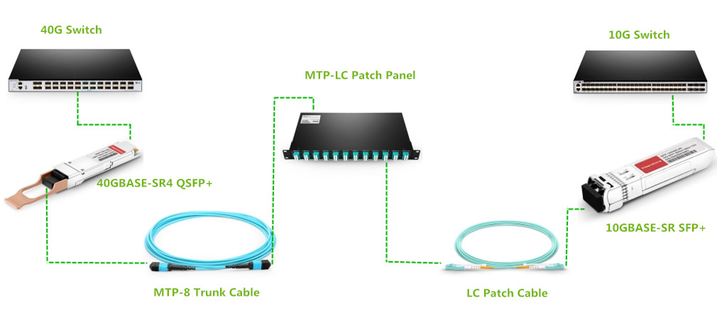
Besides using MTP breakout cable to achieve 10G to 40G migration, you can also use the MTP LC patch panel to fulfill 40G data transmission. The picture below shows the connectivity method. The 96 fibers MTP LC patch panel acts as a middleman between 10G to 40G connection. It has twelve 8-fiber MTP adapters on the rear and twelve 8 fiber LC adapters on the front. The MTP LC patch panel connects 40G QSFP ports with MTP trunk cable to the back of patch panel and then breaks out as 48 x 10G on the front with LC patch cords.

MTP-8 to LC patch panel in 10G/40G migration 

Summary
 
Supporting the current and future 8-fiber applications, MTP-8 is considered as the most efficient and the most future-proof connectivity solution. Anyone with a near-tern migration plan to adopt 40G or 100G in the data center will find great benefits in adopting MTP-8 connectivity solution. In all, MTP-8 solution can ensure data centers have the most cost-effective, future-proof network available, with a easier migration path that scales out to 400G transmission.