2017年1月22日星期日

How to Install and Connect CWDM System?

CWDM system is able to provide optical networking support for high-speed data communication for metropolitan area networks (MANs). And in some previous articles, I have talked a lot about CWDM, such as the components used in CWDM system. In this article, I’d like to have an introduction to CWDM system installation and connection.

Procedures for CWDM System Installation
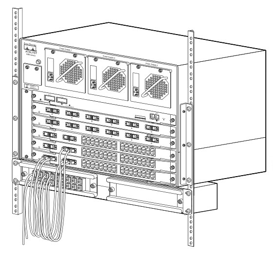
The CWDM system includes the system shelf, CWDM OADM, CWDM Mux/Demux and CWDM transceivers. You must first install the system shelf, then the CWDM OADM and CWDM Mux/Demux, followed by the CWDM transceivers you want to install.

Install the System Shelf
Follow the steps below to mount the system shelf on an equipment rack:

1. Align the mounting holes in the L brackets with the mounting holes in the equipment rack.

2.Secure the system shelf using four screws through the elongated holes in the L bracket and into the threaded holes in the mounting post.
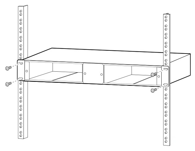
secure system shelf 

3.Use a tape measure and level to ensure that the system shelf is mounted straight and level.
 
Install the CWDM OADM and CWDM Mux/Demux (Plug-in Module)
1.Loosen the captive screws on the blank plug-in module faceplate and remove the faceplate.

2.Align the plug-in module with the slot on the system shelf.
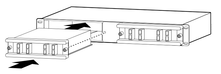
install cwdm mux 

3.Gently push the plug-in module into the system shelf slot. Ensure that you line up the captive screws on the plug-in module with the screw holes on the shelf.

4.Tighten the captive screws.

Remove the CWDM OADM and CWDM Mux/Demux (Plug-in Module)
1.Loosen the captive screws on each side of the plug-in module using a screwdriver.

2.Gently pull on both captive screws to release the plug-in module from the shelf.

3.Pull the plug-in module out of the shelf.

4.Replace the blank plug-in module faceplate if you do not intend to install another plug-in module.

Install a CWDM Transceiver
1.Remove the CWDM transceiver from its protective packaging.

2.Verify that the CWDM transceiver is the correct model for your network configuration.

3.Remove the dust covers from the CWDM transceiver’s optical bores.

4.Grasp the sides of the CWDM transceiver with your thumb and forefinger.

5.Insert the CWDM transceiver into the correct slot on your switching module. You should hear a click when the transceiver has been properly seated into the slot.

Remove a CWDM Transceiver
1.Disconnect the fiber optic patch cable.

2.Release the CWDM transceiver from the slot by simultaneously squeezing the plastic tabs.

3.Pull the CWDM transceiver out of the slot.

4.Install the plug in the CWDM transceiver optical bores and place the CWDM transceiver in protective packaging.

Procedures for CWDM System Connection
This part tells how to connect the CWDM system to the switch.

Connect Cables to a CWDM OADM
1. Insert the CWDM transceivers into the appropriate connectors on your switch if you have not already done so.

2. Insert the CWDM transceivers (color code/wavelength specific) into their respective switching module ports.

3. Clean all fiber optic connectors on the cabling before inserting them into the CWDM Mux/Demux connectors.

4. Connect the single-mode fiber optic patch cable from the CWDM transceiver (TX/RX) to the OADM module equipment connectors (TX/RX).

5. If you are using both channels of the CWDM OADM, then repeat step 4 for the second channel.

6. Connect the west backbone single-mode fiber patch cable to the OADM network west connector and connect the east backbone single-mode fiber patch cable to the OADM network east connector.
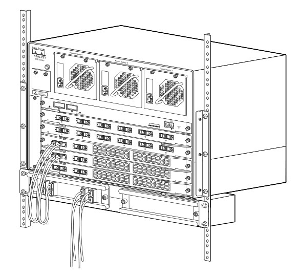
install CWDM OADM 

Connect Cables to a CWDM Mux/Demux (8-Channel)
1.Insert the CWDM transceivers (color code/wavelength specific) into their respective switches.

2.Clean all fiber optic connectors on the cabling before inserting into them into the 8-channel CWDM Mux/Demux connectors.

3.Connect the single pair fiber optic cables from the CWDM transceivers (TX/RX; up to eight channels) to the OADM module equipment connectors (TX/RX; up to eight wavelengths).

4.Connect the backbone single pair fiber optic patch cables to the OADM network connector.

5.Connect the fiber optic patch cables from the CWDM transceivers (TX/RX) to the 8-channel Mux/Demux (TX/RX) connectors.
install CWDM MUX/DEMUX 

Summary
This article provides installation instructions for the CWDM system, which includes the system shelf installation, CWDM OADM and CWDM Mux/Demux installation and removal, CWDM transceivers installation and removal as well as connecting the CWDM OADM and CWDM Mux/Demux to the switch. The optical components used in this process are as follows.

Originally published: www.fiberopticshare.com/install-connect-cwdm-system.html

2017年1月13日星期五

Introduction to the Components Used in CWDM System

CWDM system is a passive optical solution for increasing the flexibility and capacity of existing fiber lines in high-speed networks. It increases fiber capacity by placing widely spaced, separate wavelengths (between 1310 nm and 1610 nm) from multiple ports onto a single-mode fiber pair on the network. The CWDM system components are passive and require no power supplies. This article will introduce the components used in CWDM system.

CWDM System Components
 
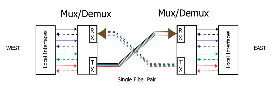
Generally, there are three basic components in a CWDM system, which are the multiplexer/demultiplexer (Mux/Demux), the drop/pass module and drop/insert module. CWDM applications are described in terms of an east-west connection. Different colors represent individual channels. Westbound traffic is represented by dashed lines, while eastbound traffic is shown with solid lines.

mux/demux 

Mux/Demux
 
The Mux/Demux based on film filter is the most mature component used in CWDM system. It combines different channels onto a single outbound (TX) fiber. Simultaneously, the Mux/Demux receives the same channels from a single inbound (RX) fiber, separates them into individual wavelengths, and delivers each to the appropriate local interface. This process expand the capacity of the existing network fiber cable. The following is an example of four channel Mux/Demux.

Mux/Demux 

The four-channel Mux/Demux can be configured to support additional channels through the expansion port. By cascading the modules in series, you can increase the total number of available network channels. The channels connecting to the expansion port must differ from those on the Mux/Demux to which they are being cascaded.

Drop/Pass Module
 
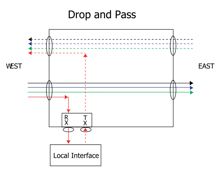
The drop/pass module removes one wavelength-specific channel from the east-bound fiber and allows the remaining channels to pass straight through to other nodes along the network. When the drop/pass module drops the channel from the network, it sends the data to a local interface. The local interface sends the same channel back to the drop/pass module for transmission in the westbound direction, thus completing the point-to-point connection between the local interface and another device located in the west. That other device may be a Mux/Demux, drop/pass, or drop/insert module.

drop and pass 

Drop/Insert Module
 
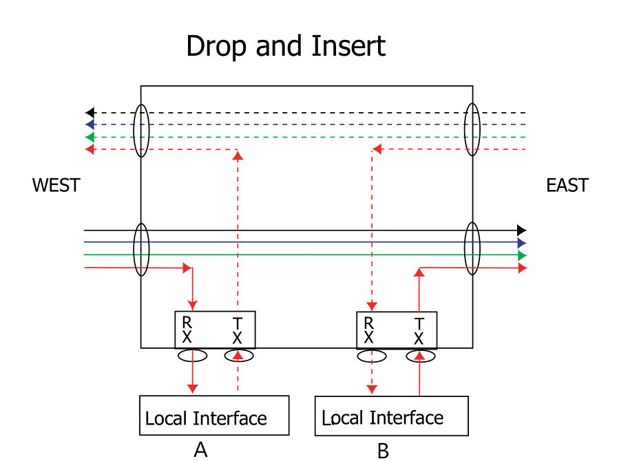
The drop/insert module provides two local interface ports. One port removes a wavelength-specific channel from the network fiber in one direction, and the other port adds that same channel back onto the fiber in the opposite direction. Because the drop/insert module supports two separate pathways going in opposite directions, network viability in a ring topology is ensured even if there is a break in the network.

On the west side, the drop/insert module removes a wavelength-specific channel from the eastbound fiber and sends it to Local Interface A. To complete the westbound connection, the drop/insert module receives the same channel from Local Interface A and inserts it onto the westbound fiber. The same happens on the east side, except in the opposite direction. The drop/insert module removes the channel from the westbound fiber and sends it to Local Interface B. To complete the eastbound connection, the drop/insert module receives the same channel from Local Interface B and inserts it onto the east-bound fiber. The drop and insert completes the point-to-point connections between the two local interfaces and two other devices located in the east and west. The other device may be a Mux/Demux, drop/pass, or drop/insert module.

drop and insert 

Summary
 
CWDM is a simple and affordable method to maximize existing fiber by decreasing the channel spacing between wavelengths. Since CWDM is a passive technology, it allows for any protocol to be transported over the link, as long as it is at a specific wavelength. Because the multiplexers simply refract light at any network speed, regardless of the protocol being deployed, CWDM can help to future proof the networking infrastructure. In all, CWDM is a low-cost and effortless technology to implement. FS.COM provides a whole series of WDM system components including CWDM and DWDM. If you need, you can visit www.fs.com for the details.


Related article: Traditional CWDM Mux/DeMux vs. FMU Series CWDM Mux/DeMux

2017年1月6日星期五

Managed Media Converter and Unmanaged Media Converter Basics

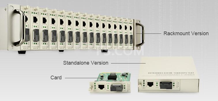
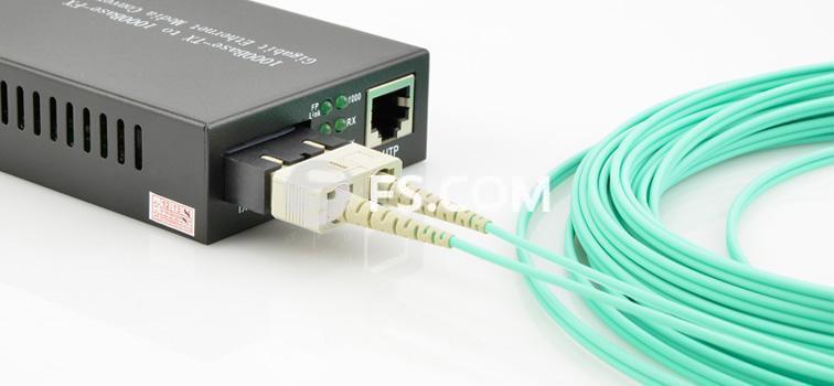
As is known to all, fiber media converter is a simple networking device which can connect two dissimilar media types such as twisted pair cable with fiber optic cable. And it can support many different data communication protocols including Ethernet, Fast Ethernet, Gigabit Ethernet, etc. According to the network to points, media converters can be divided into managed media converters and unmanaged media converters. This article will tell about these two kinds of media converters.

What Is Managed Media Converter?
 
Managed media converter supports carrier-grade network management. It is more costly than the unmanaged media converter, but it has the ability to provide additional network monitoring, fault detection and remote configuration functionality not available with an unmanaged media converter. Typically, managed media converters are equipped with remote Web / SNMP (Simple Network Management Protocol) interface, which enables network administrators to easily monitor and setup the converter, the transmission speed and duplex through web/SNMP browsers. The managed media converters are mostly suitable for those environments requiring a medium to large-scale deployment of media converters. Managed 10/100/1000 Ethernet media converter module is the smart choice for IT professionals.

managed media converter
 
What Is Unmanaged Media Converter?
 
Unmanaged media converter simply allows devices to communicate, and does not provide the same level of monitoring, fault detection and configuration as equivalent managed media converter. Connect the devices to the unmanaged media converter and they usually communicate automatically. With “plug and play” feature, unmanaged media converters are easy to install and troubleshoot. But the advantage is when a network issue is occurring, there is no way to access the media converter to see exactly what might be causing the issue. Unmanaged media converter is a great choice for newbies if you want a plug and play fiber network cable installation.

unmanaged media converter
 
When and Where to Use?
 
The managed media converters are aimed at users that require a response time of milliseconds. They are especially suitable for organizations that need to manage and troubleshoot the network remotely and securely, allowing network managers to reach optimal network performance and reliability. They can be used on any segment of a network where the traffic has to be monitored and controlled as they enable complete control of data, bandwidth and traffic. The unmanaged media converters are mostly used to connect edge devices on network spurs, or on a small stand-alone network with only a few components. They are suitable for any network that wants to simplify the installation of access points.

Summary
 
This article describes some basic information about the managed media converters and unmanaged media converters as well as their usage. The information may not be comprehensive. It’s just a reference. As a leading supplier in optical communication industry, FS.COM provides a series of managed and unmanaged media converters with various configurations. For the details, you can visit www.fs.com or contact us over sales@fs.com.