2016年11月18日星期五

Mode Conditioning Patch Cables Overview

Fiber optic patch cables play an important role in fiber optic connection. There are numbers of fiber patch cables on the market, ranging from the standard fiber patch cables to special fiber patch cables, such as mode conditioning patch cables, bend insensitive patch cables, traceable fiber patch cables, etc. This article will not introduce all of these fiber jumpers, only focus on the mode conditioning patch cables.
 
Why Need Mode Conditioning Cables?
 
Transceiver optics used in Gigabit Ethernet (1000BASE-LX) launch only single-mode long wave signals (1310 nm). This poses a problem if an existing fiber network utilizes multimode cables. When a single-mode signal is launched into a multimode fiber, the phenomenon known as DMD (differential mode delay) can create multiple signals within the multimode fiber. This effect can confuse the receiver and produce errors. Mode conditioning cables utilize an offset between the single-mode fiber and multimode fiber to eliminate DMD and the resulting multiple signals allowing use of 1000BASE-LX over existing multimode fiber cable system.

What Are Mode Conditioning Fiber Patch Cables?
 
Mode conditioning patch cables are required when Gigabit 1000BASE-LX routers and switches are installed into existing multimode cable plants. They are used to adapt the single-mode output of Gigabit Ethernet (1000BASE-LX) transceivers to a multimode cable network. They are fully compliant with IEEE 802.3z application standards.
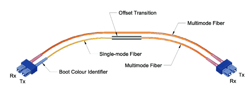

Mode conditioning patch cable 

The conditioned channel of mode conditioning patch cables consists of a single-mode fiber which has been fusion spliced to a multimode fiber in an offset manner, with a precise core alignment and angle. The non-conditioned channel of mode conditioning patch cables consists of one length of multimode cable. Light is launched on to the multimode fiber of the conditioned channel at a specific angle, giving the patch cord its mode conditioning properties. The fusion splice is protected by a black over-wrap. The other side has both a multimode and single-mode cable end. This side of the cable connects to the Gigabit transceiver equipment with the single-mode leg connecting to the transmit side. The side has two multimode cable ends connecting to the cable plant.

Things You Should Know When Using Mode Conditioning Patch Cables
 
Use mode conditioning patch cables in pairs. It means that you will need a mode conditioning patch cable at each end to connect the equipment to the cable plant. So then these cables are usually ordered in even numbers. The only reason to order an odd number of mode conditioning cables is to have a spare on hand. Mode conditioning patch cables can only convert single-mode to multimode. If you want to convert multimode to single-mode, then a media converter will be required.

If your Gigabit LX switch is equipped with SC or LC connectors, please be sure to connect the yellow leg (single-mode) of the cable to the transmit side, and the orange leg (multimode) to the receive side of the equipment. It is imperative that this configuration be maintained on both ends. The swap of transmit and receive can only be done at the cable plant side.

Mode conditioning patch cables 

If some customers remain reluctant to deploy MCP cables, and for customers using OM3 or OM4 cables, please measure the power level before plugging the fiber into the adjacent receiver. When the received power is measured above -3dBm (in 1000BASE-LX links), a 5-dB attenuator for 1300 nm should be used and plugged at the transmitter source of the optical module on each side of the link. Actually, OM3/OM4 MCP can also work in this event. While whether all multimode fiber types require mode conditioning, you can contact the manufacturer of your installed cable for the answer.

Summary
 
Mode conditioning patch cables are duplex multimode cords that have a small length of single-mode fiber at the start of the transmission leg. The basic principle behind the cords is that you launch your laser into the small section of single-mode fiber. The other end of the single-mode fiber is coupled to multimode section of the cable with the core offset from the center of the multimode fiber. FS.COM provides various types of mode conditioning patch cables with different connectors. All these mode conditioning patch cables are in high quality and low price. For more details, welcome to visit www.fs.com or contact us over sales@fs.com.

2016年11月10日星期四

Introduction to the Components Used in DWDM System

DWDM is an innovation that enables multiple optical carriers to travel in parallel in a fiber. DWDM devices combine the output from several optical transmitters for transmission across a single fiber. At the receiving end, another DWDM device separates the combined optical signals and passes each channel to an optical receiver. Only one optical fiber is used between DWDM devices (per transmission direction). How DWDM system works, and what components are needed in DWDM system? Keep reading this article and you will find the answer.

Components Used in DWDM System
 
Typically, the components used in a DWDM system include optical transmitters and receivers, DWDM mux/demux, OADM (optical add/drop multiplexers), optical amplifiers and transponders (wavelength converters). Following part will introduce these devices respectively.

Optical Transmitters and Receivers
 
Transmitters are described as DWDM components because they provide the source signals which are then multiplexed. The characteristics of optical transmitters used in DWDM systems is highly important to system design. Multiple optical transmitters are used as the light sources in a DWDM system which requires very precise wavelengths of light to operate without interchannel distortion or crosstalk. Several individual lasers are typically used to create the individual channels of a DWDM system. Each laser operates at a slightly different wavelength.

DWDM Mux/DeMux
 
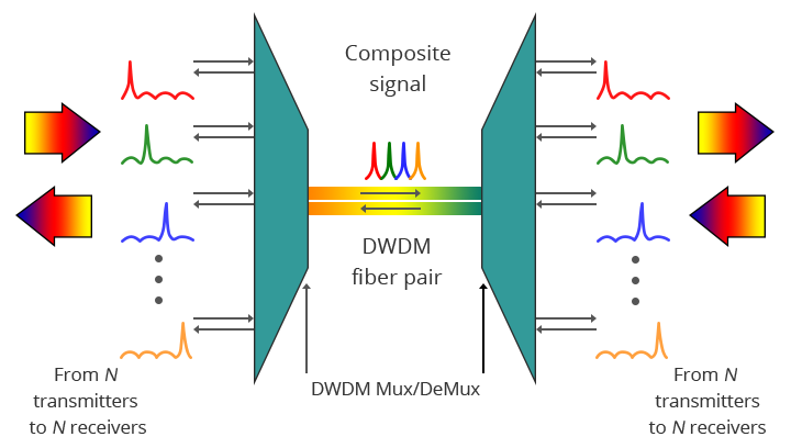
The DWDM Mux (multiplexer) combines multiple wavelengths created by multiple transmitters and operating on different fibers. The output signal of an multiplexer is referred to as a composite signal. At the receiving end, the DeMux (demultiplexer) separates all of the individual wavelengths of the composite signal out to individual fibers. The individual fibers pass the demultiplexed wavelengths to as many optical receivers. Generally, Mux and DeMux components are contained in a single enclosure. Optical Mux/DeMux devices can be passive. Component signals are multiplexed and demultiplexed optically, not electronically, therefore no external power source is required.

DWDM Mux/DeMux 

The picture above shows the bidirectional DWDM operation. N light pulses of N different wavelengths carried by N different fibers are combined by a DWDM Mux. The N signals are multiplexed onto a pair of optical fibers. A DWDM demultiplexer receives the composite signal and separates each of the N component signals and passes each to a fiber. The transmit and receive signal arrows represent client-side equipment. This requires the use of a pair of optical fibers—one for transmit and the other for receive.

OADM
 
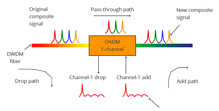
OADM is often a device found in WDM systems for multiplexing and routing different channels of fiber into or out of a single-mode fiber (SMF). It is created to optically add/drop one or multiple CWDM/DWDM channels into a few fibers, providing the power to add or drop a single wavelength or multi-wavelengths from a fully multiplexed optical signal. This permits intermediate locations between remote sites gain access to the regular, point-to-point fiber segment linking them. Wavelengths not dropped pass-through the OADM and carry on towards the remote site. Additional selected wavelengths may be added or dropped by successive OADMs if required.

DWDM OADM 

The picture above demonstrates the operation of a one-channel OADM. This OADM is designed to only add or drop optical signals with a particular wavelength. From left to right, an incoming composite signal is broken into two components, drop and pass-through. The OADM drops only the red optical signal stream. The dropped signal stream is passed to the receiver of a client device. The remaining optical signals that pass through the OADM are multiplexed with a new add signal stream. The OADM adds a new red optical signal stream, which operates at the same wavelength as the dropped signal. The new optical signal stream is combined with the pass-through signals to form a new composite signal.

Optical Amplifiers
 
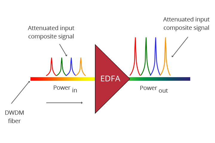
Optical amplifiers boost the amplitude or add gain to optical signals passing on a fiber by directly stimulating the photons of the signal with extra energy. They are “in-fiber” devices. Optical amplifiers amplify optical signals across a broad range of wavelengths, which is very important for DWDM system application.

EDFA 

Transponders (Wavelengths Converters)
 
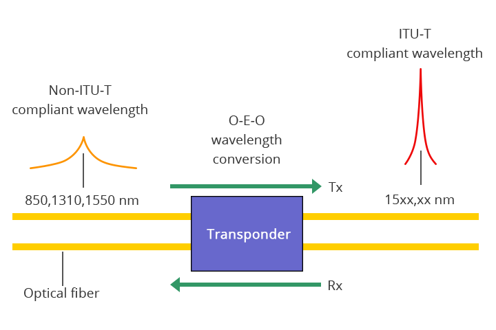
Transponders convert optical signals from one incoming wavelength to another outgoing wavelength suitable for DWDM applications. Transponders are optical-electrical-optical (O-E-O) wavelength converters. A transponder performs an O-E-O operation to convert wavelengths of light. Within the DWDM system, a transponder converts the client optical signal back to an electrical signal (O-E) and then performs either 2R (reamplify, reshape) or 3R (reamplify, reshape and retime) functions.

transponders 

The picture above shows bi-directional transponder operation. A transponder is located between a client device and a DWDM system. From left to right, the transponder receives an optical bit stream operating at one particular wavelength (1310 nm). The transponder converts the operating wavelength of the incoming bit stream to an ITU-compliant wavelength. It transmits its output into a DWDM system. On the receive side (right to left), the process is reversed. The transponder receives an ITU-compliant bit stream and converts the signals back to the wavelength used by the client device.

Summary
 
This article provides some basic information about the components used in a DWDM system. All of the components compose the integrated DWDM system. And they are indispensable. Hope the information in this article is helpful when building your DWDM system.

2016年11月1日星期二

Understanding the Split Ratios and Splitting Level of Optical Splitters

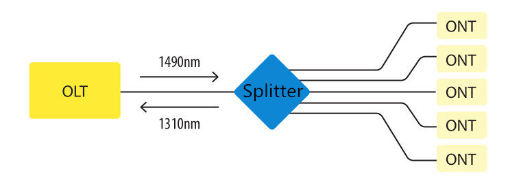
Optical splitters play an important role in FTTH PON networks where a single optical input is split into multiple output, thus allowing a single PON interface to be shared among many subscribers. The optical splitters have no active electronics and don’t require any power to operate. They are typically installed in each optical network between the PON OLT (optical line terminal) and ONTs (optical network terminals) that the OLT serves. Generally, two kinds of fiber optic splitters are popular, which are FBT splitters and PLC splitters. The differences between the two have been stated in another article—FBT Splitters vs. PLC Splitters: What Are the Differences? So it is unnecessary to go into the details here. Besides these, what other information do you know about optical splitters? Keep reading this article, you may get more about 
it.

fiber optic splitter 

Split Ratios
 
There are a multitude of split ratios available. The most common splitters deployed in a PON system is a uniform power splitter with a 1:N or 2:N splitter ratio, where N is the number of output ports. The optical input power is distributed uniformly across all output ports. Splitters with non-uniform power distribution is also available but such splitters are usually custom made and command a premium. Generally, the 1:N splitters are deployed in star networks, while 2:N splitters are deployed in ring networks to provide physical network redundancy.

1:N splitter and 2:N splitter 

The use of optical splitters in PON allows the service provider to conserve fibers in the backbone, essentially using one fiber to feed as many as 64 end users. A typical split ratio in a PON application is 1:32, meaning one incoming fiber split into 32 outputs. And the qualified fiber optic signal can be transmitted over 20 km. If the distance between the OLT and ONT is small (in 5 km), you can consider about 1:64. With higher split ratios, the PON network has both advantages and disadvantages. Fiber optic splitters with higher split ratios can share the OLT optics and electronics costs as well as share feeder fiber costs and potential new install costs. In addition, larger splits allow more flexibility and fiber management at head end is simpler. At the same time, higher split ratio splitters reduce bandwidth per ONU (optical network unit). And there will be increased optics cost either at OLT or ONU or both to achieve large optical power budgets.

Splitting Level
 
In the PON network, there are two common splitter configurations—centralized approach and cascaded approach.

Centralized Approach
 
The centralized splitter approach typically uses a 1x32 splitter in an outside plant (OSP) enclosure, such as a fiber distribution terminal. The 1x32 splitter is directly connected via a single fiber to an OLT in the central office. On the other side of the splitter, 32 fibers are routed through distribution panels, splice ports or access point connectors to 32 customers’ homes, where it is connected to an ONT. Thus, the PON network connects one OLT port to 32 ONTs.

centralized splitter 

Cascaded Approach
 
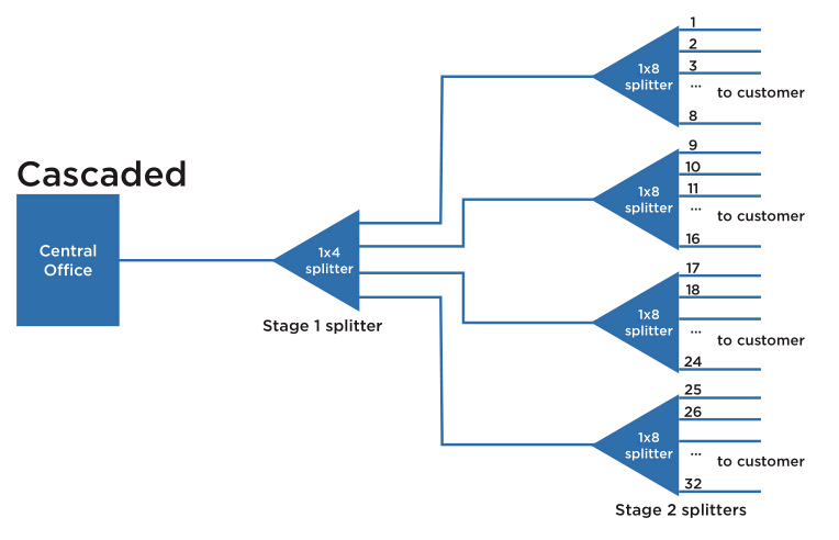
The cascaded approach may use a 1x4 splitter residing in an outside plant enclosure. This is directly connected to an OLT port in the central office. Each of the four fibers leaving this stage 1 splitter is routed to an access terminal that houses a 1x8, stage 2 splitter. In this scenario, there would be a total of 32 fibers (4x8) reaching 32 homes. It is possible to have more than two splitting stages in a cascaded system, and the overall split ratio may vary (1x16=4x4, 1x32=4x8, 1x64=4x4x4).

cascaded splitter 

Which to Choose?
 
It is important to understand both architectures in detail and weigh the trade-offs when deciding on the best approach. For most applications, the centralized approach is recommended.

First and foremost, the centralized approach maximizes the highest efficiency of expensive OLT cards. As each home in this approach is fiber-connected directly back to a central hub, there are no unused ports on the OLT card and 100% efficiency is achieved. This also allows a much wider physical distribution of the OLT ports—extremely important when initial “take rates” are projected to be low to moderate. Secondly, centralized approach is able to provide easy testing and troubleshooting access. The centralized 1x32 splitter with distribution ports enables OTDR trace development upstream to the central office and downstream to the access terminal. Also the connector ports available at the distribution hub enable qualification testing of the distribution cabling. Thirdly, loss will occur when splitters are cascaded together. The combined loss effect can reduce the distance a signal can travel, imposing distance limitations on fiber runs. The centralized splitter minimizes that signal loss by eliminating extra splices or connectors from the distribution network.

In general, the centralized architecture typically offers greater flexibility, lower operational costs and easier access for technicians, while the cascaded approach may yield a faster return-on-investment, lower first-in costs and lower fiber costs.

Summary
 
This article has reviewed some information about the split ratios and splitting level of fiber optic splitters. It is very essential to make clear all these different configurations, or the network performance will be influenced if misunderstanding or misusing the optical splitters. Hope the information in this article can help when needed.