2016年10月25日星期二

Guide for Choosing the Right Fiber Optic Cable

Fiber optic cable is a very thin glass strand through which a pulse of light is transmitted. Nowadays, fiber optic cable is a desirable cable medium due to its immunity to electromagnetic interference (EMI) and radio frequency interference (RFI). It can transport optical signals for significant distances, whether in local area, wide area, or in metropolitan area. This article will tell some information about fiber optic cables and aim at providing a guideline on choosing the right fiber optic cable.

Single-mode or Multimode Fiber Optic Cable
 
Fiber optic cable can be divided into single-mode fiber cable and multimode fiber cable. Single-mode optical fiber generally has a core diameter of 9 µm and requires laser technology for sending and receiving data. It can carry a signal for miles, which makes it ideal for telephone and cable television providers. As the name suggests, multimode fiber permits the signal to travel in multiple modes, or pathways, along the inside of the glass strand or core. It is available with fiber core diameters of 62.5 µm or 50 µm. Although the core sizes of single-mode fiber and multimode fiber differ, both fiber types end up with an outer diameter of about 250 µm. The key differences between the two kinds of fiber optic cables have been illustrated more clearly in another article—Single-mode Fiber vs. Multimode Fiber: Which to Choose?
 
Indoor Cables or Outdoor Cables
 
The major difference between indoor cables and outdoor cables is water blocking. Any conduit is someday likely to get moisture in it. Outdoor cables are designed to protect the fibers from years of exposure to moisture. Indoor cables are what we call “tight-buffered” cables, where the glass fiber has a primary coating and secondary buffer coatings that enlarge each fiber to 900 microns—about 1mm or 1/25-inch, to make fiber easier to work with.

Indoor Cables
 
Usually, indoor cables include simplex and zipcord, distribution cables and breakout cables. Simplex fiber optic cables are one fiber, tight-buffered (coated with a 900 micron buffer over the primary buffer coating) with Kevlar (aramid fiber) strength members and jacketed for indoor use. The jacket is typically 3mm (1/8 in.) diameter. Zipcord is simply two of these jointed with a thin web. It’s used mostly for patch cord and backplane applications, but zipcord can also be used for desktop connections.

Distribution cables contain several tight-buffered fibers bundled under the same jacket with Kevlar strength members and sometimes fiberglass rob reinforcement to stiffen the cable and prevent kinking. These cables are small in size, and used for short, dry conduit runs, riser and plenum applications. The fibers are double buffered and can be directly terminated, but because their fibers are not individually reinforced, these cables need to be broken out with a “breakout box” or terminated inside a patch panel or junction box. The distribution cable is the most popular cable for indoor use.
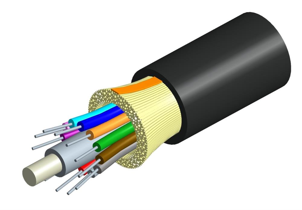
distribution fiber optic cable 

Breakout cables are made of several simplex cables bundled together inside a common jacket for convenience in pulling and ruggedness. This is a strong, rugged design, but is larger and more expensive than the distribution cables. They are suitable for conduit runs, riser and plenum applications, and ideal for industrial applications where ruggedness is important or in a location where only one or two pieces of equipment need to be connected.
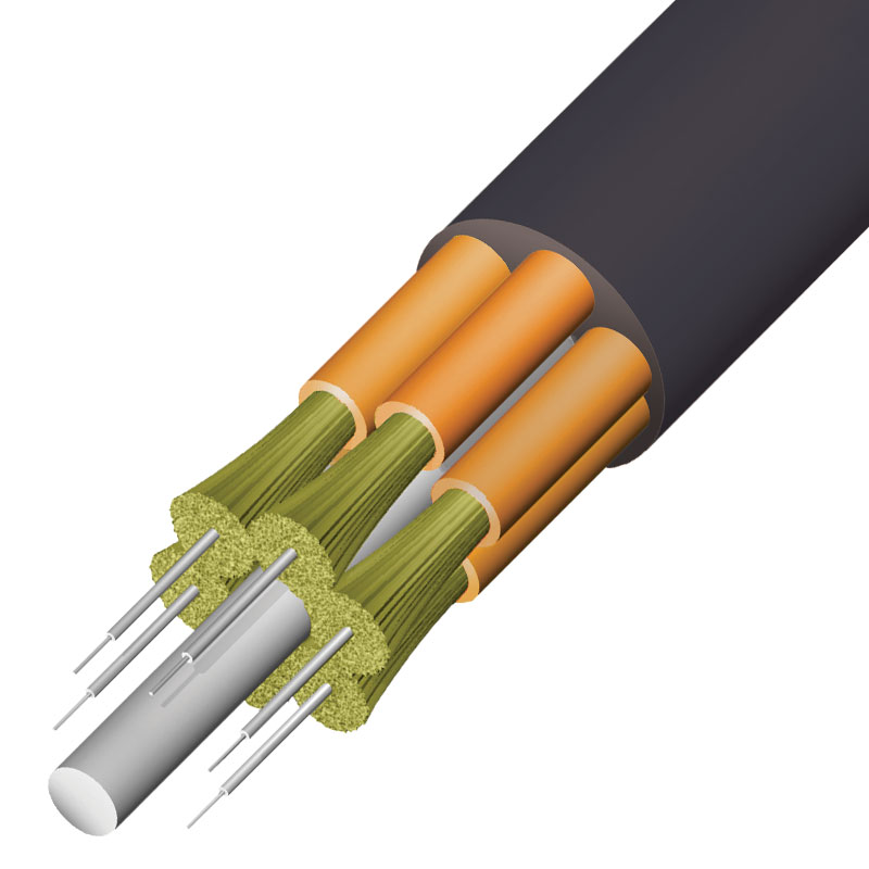
breakout fiber optic cable 

Outdoor Cables
 
Fiber optic cables in outdoor applications require more protection from water ingress, vermin and other conditions encountered underground. Outdoor cables need increased strength for greater pulling distances. Generally, fiber optic cables installed in outdoor applications contain loose tube fiber optic cable, ribbon fiber optic cable, armored fiber optic cable and aerial fiber optic cable.

Loose tube fiber optic cables are composed of several fibers together inside a small plastic tube, which are in turn wound around a central strength member and jacketed, providing a small, high fiber count cable. They are suitable for outside plant trunking applications because they can be made with loose tubes filled with gel or water absorbent powder to prevent harm to the fibers from water. Since the fibers have only a thin buffer coating, they must be carefully handled and protected to prevent damage. They can be used in conduits, strung overhead or buried directly into the ground.
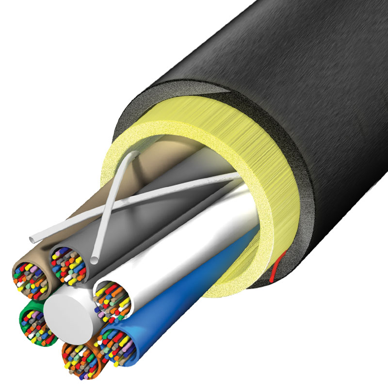
loose tube fiber optic cable 

Ribbon fiber optic cables offer the highest packing density as all the fibers are laid out in rows, typically of 12 fibers, and laid on top of each other. In this way, 144 fibers only have a cross section of about 1/4 inch or 6mm. Some cable designs use a slotted core with up to 6 of these 144 fiber ribbon assemblies for 864 fibers in one cable. Because they are outside plant cables, they are gel-filled for water blocking.
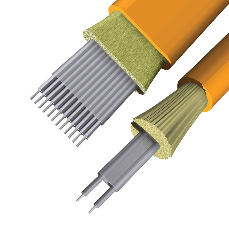
ribbon fiber optic cable 

Armored fiber optic cables are installed by direct burial in areas where rodents are a problem. Usually they have metal armored between two jackets to prevent rodent penetration. This means the cable is conductive, so it must be grounded properly. It is best to choose armored fiber optic cable when use cable directly buried outdoor. Aerial fiber optic cables can be lashed to a messenger or another cable (common in CATV) or have metal or aramid strength members to make them self-supporting. Aerial cables are for outside installation on poles.
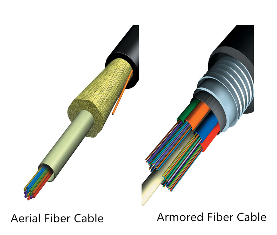
armored and aerial fiber optic cable 

Cable Jackets: PVC (OFNR), OFNP, or LSZH
 
Cable jackets can provide strength, integrity and overall protection of the fiber member. PVC is widely used as a cable jacket for many applications—computers, communications, low-voltage wiring, etc. PVC can potentially be dangerous in a fire situation, releasing heavy smoke and hydrogen chloride gas, which can be irritating to humans and corrosive to electronic devices. OFNP, or plenum jackets, are suitable for use in plenum environments such as drop-ceilings or raised floors. Many data centers and server rooms have requirements for plenum-rated cables. LSZH is a jacket made from special compounds which give off very little smoke and no toxic halogenic compounds when burned.

Summary
 
When choosing the fiber optic cables, please always remember the elements mentioned in this article. Only make clear all these aspects can you select the fiber optic cable that most suits your applications. If you are still confused about which one to choose, you can visit www.fs.com or contact sales@fs.com to seek help as lots of professional advice can be given by FS team.

2016年10月24日星期一

Traditional CWDM Mux/DeMux vs. FMU Series CWDM Mux/DeMux

With the need for bandwidth increasing, the WDM (wavelength division multiplexing) technology was developed to expand network capacity over a single fiber. It uses a multiplexer (Mux) at the transmitter to combine several signals together, and a demultiplexer (DeMux) at the receiver to split them apart. Most WDM systems operate on 9µm single-mode fiber optical cables. And they are divided into CWDM (coarse wavelength division multiplexing) and DWDM (dense wavelength division multiplexing). This article mainly focuses on CWDM system.

CWDM Mux/DeMux Overview
 
CWDM is a technology which multiplexes multiple optical carrier signals on a single optical fiber by using different wavelengths/colors of laser light to carry different signals. In a CWDM system, the CWDM Mux/DeMux is one of the most important component.

The CWDM Mux/DeMux modules are passive optical solutions which are easy to operate with a reliable low-maintenance design, and do not use power supplies or electronics. They are designed to provide optical networking support for high-speed Fibre Channel and Ethernet communication for MAN (metropolitan area network) over a grid of CWDM optical wavelengths. CWDM Mux/DeMux is capable of multiplexing and demultiplexing wavelengths up to 18 channels from 1270 nm to 1610 nm in 20nm increments. Moreover, it works seamlessly with transceivers to optimize link length, signal integrity and network cost, and can be incorporated into a single rack-mount solution for enhanced design, power and space efficiency.

Traditional CWDM Mux/DeMux System
 
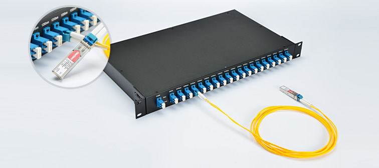
Typically, the CWDM Mux/DeMux modules interface to CWDM SFP/SFP+/XFP transceivers on an attached FC SAN or network device. This chassis-based system allows the addition of CWDM capability to any existing SAN or network device that supports LC SFP/SFP+/XFP transceivers. In short, the CWDM Mux/DeMux modules is connected with CWDM SFP/SFP+/XFP transceivers which are inserted into the switch SFP/SFP+/XFP ports by using LC single-mode patch cables.

CWDM Mux/DeMux 

The CWDM transceivers are hot-swappable, field-replaceable devices that adapt an electronic data signal to laser light at a specific wavelength. Moreover, they are color-coded to indicate the wavelength and have a color-coded clasp at one end. So the CWDM Mux/DeMux should be connected with the CWDM transceivers with the same wavelength as each transceiver will work only at the appropriate port and the data will always flow between devices with the same wavelengths. For instance, the port on the CWDM Mux/DeMux marked with 1470 nm, should be connected with the CWDM transceiver that works over 1470nm wavelength. As CWDM Mux/DeMux supports up to 18 different wavelengths, there are CWDM transceivers working over these 18 wavelengths. The following table lists the 1000BASE-CWDM SFP (20km) transceivers as an example.

Model IDWavelengthDescription
339791270 nm1000BASE-CWDM SFP 1270nm 20km DOM Transceiver
373191290 nm1000BASE-CWDM SFP 1290nm 20km DOM Transceiver
373211310 nm1000BASE-CWDM SFP 1310nm 20km DOM Transceiver
373201330 nm1000BASE-CWDM SFP 1330nm 20km DOM Transceiver
526741350 nm1000BASE-CWDM SFP 1350nm 20km DOM Transceiver
526751370 nm1000BASE-CWDM SFP 1370nm 20km DOM Transceiver
526761390 nm1000BASE-CWDM SFP 1390nm 20km DOM Transceiver
526771410 nm1000BASE-CWDM SFP 1410nm 20km DOM Transceiver
526781430 nm1000BASE-CWDM SFP 1430nm 20km DOM Transceiver
526791450 nm1000BASE-CWDM SFP 1450nm 20km DOM Transceiver
526801470 nm1000BASE-CWDM SFP 1470nm 20km DOM Transceiver
526811490 nm1000BASE-CWDM SFP 1490nm 20km DOM Transceiver
526821510 nm1000BASE-CWDM SFP 1510nm 20km DOM Transceiver
526831530 nm1000BASE-CWDM SFP 1530nm 20km DOM Transceiver
526841550 nm1000BASE-CWDM SFP 1550nm 20km DOM Transceiver
526851570 nm1000BASE-CWDM SFP 1570nm 20km DOM Transceiver
526861590 nm1000BASE-CWDM SFP 1590nm 20km DOM Transceiver
526871610 nm1000BASE-CWDM SFP 1610nm 20km DOM Transceiver

FMU Series CWDM Mux/DeMux System
 
FMU CWDM Mux/DeMux modules are new types of modules launched by FS.COM. Compared with the traditional CWDM Mux/DeMux modules, the new FMU series modules are more user-friendly and show completely new characteristics.

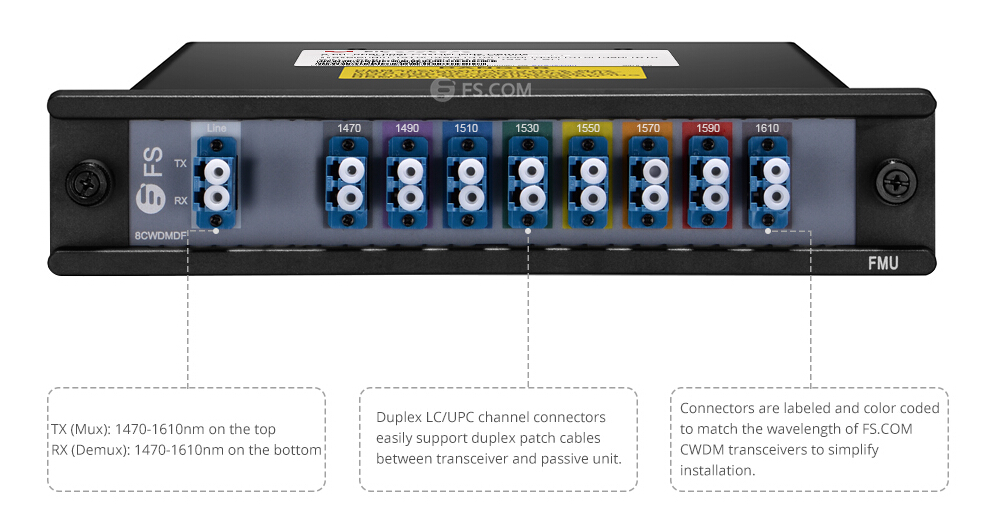
With low-profile modular design, the FMU CWDM Mux/DeMux modules plug into one half of a 1RU, 19” rack mount chassis for simple installation and modularity. This chassis based system allows a network equipment manufacture to add CWDM capability to any existing networks with simple pluggable interface. Besides, the equipment ports of the FMU CWDM Mux/DeMux modules are color-coded to match the wavelengths of CWDM transceivers to simplify installation and troubleshooting without having to remove the transceivers from the local equipment. This color-coded feature is the major advantage of this new FMU series modules and it do greatly simplify the process of connecting a CWDM transceiver to its associated device port. The following picture is an example of 8 channels 1470-1610nm dual fiber CWDM Mux/DeMux. This new FMU series CWDM Mux/DeMux modules deliver dramatic cost savings to network equipment manufacturers, enabling them to develop metro access systems that are lower in cost, easier to provision and simpler to operate.

8 channels 1470-1610nm dual fiber CWDM Mux/DeMux 

The following table lists FS.COM FMU series CWDM Mux/DeMux modules.

Model IDDescription
435544 channels 1470-1590nm single fiber CWDM Mux Demux
435534 channels 1490-1610nm single fiber CWDM Mux Demux
429724 channels 1270-1330nm dual fiber CWDM Mux Demux
429444 channels 1510-1570nm dual fiber CWDM Mux Demux
437808 channels 1290-1590nm single fiber CWDM Mux Demux
437798 channels 1310-1610nm single fiber CWDM Mux Demux
429458 channels 1290-1430nm dual fiber CWDM Mux Demux
430978 channels 1470-1610nm dual fiber CWDM Mux Demux
437119 channels 1270-1590nm single fiber CWDM Mux Demux
436999 channels 1290-1610nm single fiber CWDM Mux Demux
483934 channels 1470-1590nm single fiber CWDM Mux Demux with expansion port
483944 channels 1490-1610nm single fiber CWDM Mux Demux with expansion port
429734 channels 1510-1570nm dual fiber CWDM Mux Demux with expansion port
430998 channels 1470-1610nm dual fiber CWDM Mux Demux with expansion port
3348918 channels 1270-1610nm dual fiber CWDM Mux Demux with monitor port
304081RU Rack Mount Chassis unloaded, holds up to 2 units half 19''/1RU FMU Cassettes

Note: The modules with expansion port allows adding or expanding more CWDM wavelengths/channels to the network for future upgrade. If used, it will be treated just like the other ports and up-jacketed and terminated as needed. If not used, it will be cut back into the module and terminated in a way to reduce reflections.

Conclusion
 
Both the traditional CWDM Mux/DeMux and the FMU series CWDM Mux/DeMux are used to increase fiber network capacity without the expense of deploying more fiber cables. They make full use of the low loss bandwidth of optical fiber to achieve ultra high bit rate transmission. The key difference is that it is more convenient and efficient for the FMU CWDM Mux/DeMux to connect with the CWDM transceivers. FS.COM provides both the two kinds of CWDM Mux/DeMux modules. For more details, you can visit www.fs.com.

2016年10月14日星期五

Guide for Choosing the Suitable Ethernet Cables

Not all Ethernet cables are created equally. They are grouped into sequentially numbered categories (“cat”) based on different specifications. Generally, there are Cat 5e, Cat 6, Cat 6a, Cat 7 cables, etc. What are the differences between these different kinds of Ethernet cables? And how to choose the suitable one for your network? This article will provide some information about what should be considered when choosing.

Characteristics of Different Cables
Before choosing the Ethernet cables, we should first know the characteristics of each kind of Ethernet cable.

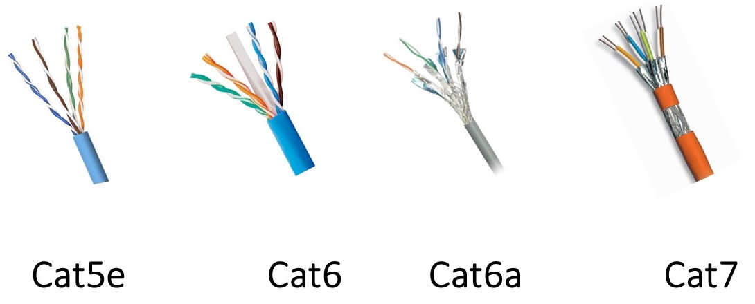
cat 5e, cat6, cat7 

Cat 5 cables are designed to support theoretical speed of between 10 Mbps and 100 Mbps. However, gigabit speeds can still be attained with Cat 5 cable particularly if the cable is shorter, but is not always a guarantee. It supports a bandwidth of up to 100 MHz. The “e” in Cat 5e stands for “enhanced” and as the name suggests, it is basically an improvement on Cat 5 cables. In theory, it should be ten times faster than the Cat 5 cables without a substantial price increase. It supports up to 1000 Mbps or gigabit speeds. The Cat 5e cables have lower crosstalk and provide a faster, reliable and steady speed than Cat 5 cable.

Cat 6 cables have more stringent specifications than Cat 5e cables and are capable of supporting 10 Gbps. They have slighter thicker wires, and the cores are more tightly twisted together. This means the cables are thicker and less flexible than Cat 5e cables. The Cat 6 cables are recommended for large organizations which deal with pretty bulk files. For home purposes, Cat 5 and Cat 5e are positively enough. Cat 6a cables have improved properties and can operate at 500 MHz and can support 10 Gbps to a maximum distance of 328 feet. It should be noted that cable termination requirements for Cat 6 and Cat 6a cables are stringent, and the cables require better protection than Cat 5e cables.

Cat 7 cables feature even more strict specifications for crosstalk and system noise than Cat 6. And shielding have been added for individual wire pairs on the Cat 7 cables. They have been designed for Gigabit Ethernet over 100 m of copper cabling, and they are rated for transmission frequencies of up to 600 MHz. Cat 7a cables operate at frequencies up to 1000 Mhz. They are designed for multiple applications in a single cable including 40G, 100G and CATV. The transmission distance can be up to 50 m for 40G, and 15 m for 100G.

Factors to Consider
Following lists two factors that should be considered when choosing the cables, which are STP/UTP cables and solid/stranded cables.

STP or UTP
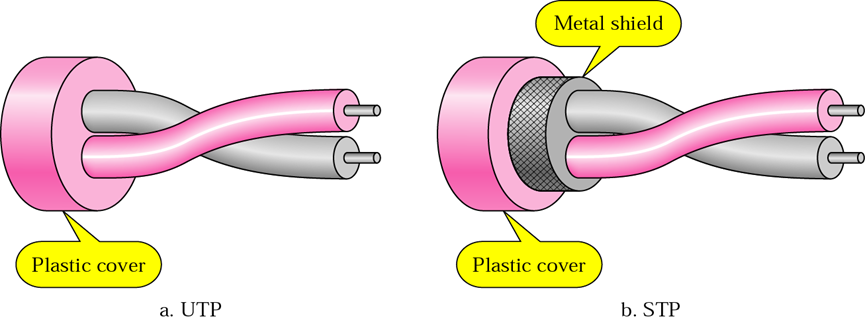
STP (shielded twisted pair) cables simply have additional shielding material that is used to cancel any external interference that may be introduced at any point in the path of the cable. UTP (unshielded twisted pair) cables have no protection against such interference and its performance is often degraded in its presence. But both of them have interference canceling capacities.

UTP, STP 

Typically, using STP cables ensures that you can get the maximum bandwidth from your cabling even if the external condition is less than ideal. STP cables work by attracting interference to the shield, then running it off into a grounded cable. If the cable is improperly grounded, then its noise-canceling capabilities are severely compromised. Additionally, STP cables have bigger diameter than UTP cables, and they are more expensive. Besides, they are more fragile as the shield must be kept intact to ensure them work properly. STP cables are commonly used in industrial settings with high amounts of electromagnetic interference, such as a factory with large electronic equipment, where they can be properly installed and maintained. They can also be used in outdoor environments where the cables are exposed to the elements and man-made structures and equipment that may introduce additional interference.

UTP cables are smaller than STP cables, which makes them easier to install, particularly in bulk or in narrow spaces. They do not require the presence of a grounding cable and do not require much maintenance, but transmit data as fast as STP cables. Generally, UTP cables are more prone to noise than properly installed and maintained STP cables. They are more prevalent and popular used in domestic and office Ethernet connections, and in any area where there is not a high degree of electromagnetic interference.

Solid or Stranded
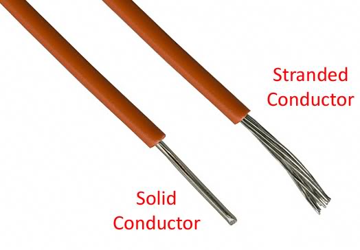
Both solid and stranded Ethernet cables refer to the actual copper conductor in the pairs. The solid cable uses one solid wire per conductor, so in a standard Cat 5e or Cat 6 four pair (8 conductor) roll, there would be a total of 8 solid wires. Stranded cable uses multiple wires wrapped around each other in each conductor, so in a 4 pair (8 conductor) 7 strand roll (typical configuration), there would be a total of 56 wires.

solid cable, stranded cable 

Solid cables are most useful for structured wiring within a building. They can be easily punched down onto wall jacks and patch panels as they have only one conductor. The wire seats properly into insulation displacement connector. Solid cables are less useful when you are terminating with standard RJ45 connectors, as used when making patch cables. Most RJ45 connectors use 2 prongs which penetrate the conductor itself. This is not desirable, since solid cable has the tendency to break when penetrated by the prong. Using a 3 prong style RJ45 connectors creates a much better connection as it doesn’t break the conductor—the 3 prongs style connection wraps around the conductor instead of penetrating it. It is recommended that stranded network cable be used for patch cables as they make better quality RJ45 termination connections than even using 3 prong connectors.

Stranded cables are much less useful for punching down on wall jacks because the strands do not keep their perfect round shape when thrust into a insulation displacement connector. For best results, use solid for wall jacks and stranded for crimp connectors. Stranded cable is typically used to create patch cables. The cable itself is more flexible, and rolls up well. The RJ45 terminators have a better, and more flexible and complete connection to stranded wires than solid wire.

Summary
Be sure to make clear of every kind of Ethernet cables and take each of the factors above into account before finally selecting the one for your home or business project. Hope the information in this article could be helpful or a guide for you when you are confused about which Ethernet cable to choose.

2016年10月5日星期三

How to Get Proper Cable Management in Data Center?

Data center is the heart that pumps the lifeblood of your business. Without it, everything stops. And when there is anything wrong in the data center, so does your business. For many data centers, managing cables is an afterthought. But actually, cable management is one of the most important aspects of data center design. Following cable management tips are helpful in the day-to-day facility management of a data center.

Measure Twice, Cut Once
It’s an old adage, but an important one. If you don’t carefully measure your cables, not only you create a tangled mess, but also you create a lot of expensive waste. You may think that two feet of wasted cables does not amount much, but when add up those wasted feet, it would be a huge cost. So please remember to measure twice while cut once to save yourself a lot of time and money.

Cable Labeling
Be it a power or data cable, labeling cables can prove to be critical if a problem arises. Cable labels should be secured in a way that will make them accessible, yet difficult to remove. If you don’t label your cables, you are only making more work for yourself. Imagine you have to test a bunch of circuits quickly. You scramble and unplug a few patch cables, and when it’s time to reset them back to their default locations, you have no idea where each cable goes. Avoid this problem by taking a little time to slap a cable label on each end.

cable label
Cable Testing
All cables should be pre-tested prior to installation. Once installed, it is much harder to test and identify problems. If a test doesn’t pass 100%, redo that cable. After a few tries at termination, if the cable still doesn’t pass, trash it. And make sure you’re using a quality tester for your cables and you know precisely how to use it. This simple step can prevent a lot of extra work in the end.

Run Cables in Hot Aisle
Proper airflow in and around the data center is critical to optimal operating efficiency. Keep underfloor power cables in the hot aisle running parallel to the computer room air conditioner (CRAC) unit’s airflow. Consider elevating mounting positions for the receptacles to help protect against possible pooling water and cable air dams, allowing for better air flow and improved CRAC unit efficiency. Running data cables only in the hot aisle, organizing cables using horizontal and vertical cable managers will help to improve airflow through the racks, avoiding hot spots and possible outages.

Cable Ties
Use cable ties to hold groups of data cables together or to secure cables to components. Velcro cable ties are versatile and can be reused or adjusted as cables are added or moved. If you use zip ties, make sure clipped ends of the ties are disposed properly and don’t end up a contaminant in the plenum cooling system.

cable tie
Color Code
Color provides quick visual identification. Color coding simplifies management and can save you time when you need to trace cables. With data cables, use color to identify their role/function of the cables or the type of connection. With power cables, use different colors to identify and organize dual power feeds for redundant power sources.

Cable Managers
Choose the best cable managers for your application. No one cable manager can be universally used. Some cable managers are simple and use hooks to organize cabling bundles. Others are more complex and allow individual cable runs to exit at various points. Some of these more elaborate cable managers have covers to hide bundles and keep your installation neat.

cable manager
Summary
This article have introduced several tips for improved cable management. It is a simple and inexpensive cable management solution to keep your data center cables organized according to predetermined scheme and routed in specified locations. Hope the cable management tips mentioned above can do you a favor in your data center cable managing.