2016年6月29日星期三

Keyed LC Connectivity Solutions Ensure a Secure Fiber Network

In recent years, physically discrete fiber connection systems have emerged to meet the ever growing demand for fiber network security. As network security can be improved with sophisticated software tools, making the right decisions in the early stage of the infrastructure design becomes imperative, for the sake of protecting the ever increasing amount of sensitive data being exchanged over today’s networks. The keyed LC connectivity solution, topic of this article, offers network users security at the physical layer.

What Is Secure Keyed LC Connectivity System?
The secure keyed LC system is designed specifically for mission critical circuits where networks are segregated by color for identification and protected from accidental moves, adds, or changes. Generally, the secure keyed LC components are available with 12 different keying options each carrying a different color to facilitate network administration. The keyed LC connectors and adapters are color coded and keyed to allow same color patching only. Different colored adapters and connectors cannot mate to allow circuit access. The twelve color-coded key combinations prevent inadvertent or unauthorized access to networks and provide fast and easy network identification.
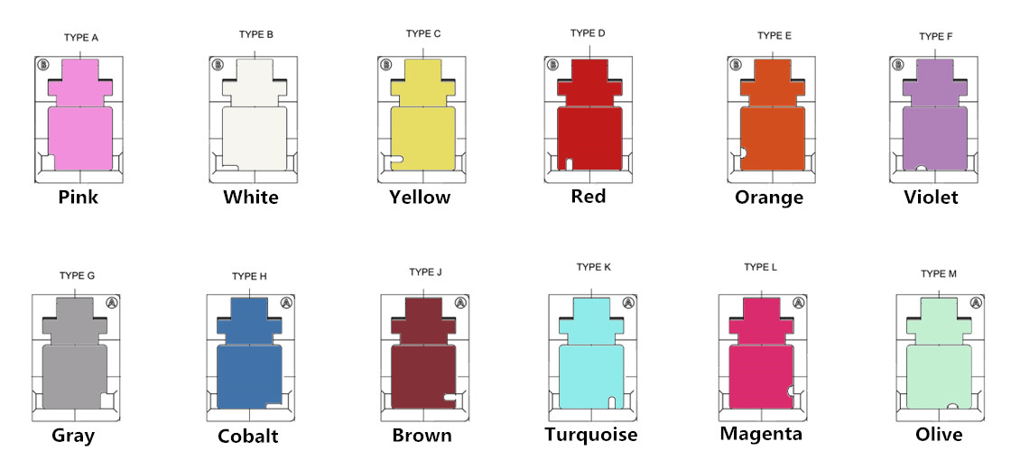

keyed LC products

Benefits of Keyed LC Connectivity Solution
The keyed LC connectivity solution allows manageable and easily identifiable network segregation by use of a range of physically unique keyed connector and adapter combinations. Each color features a unique keying pattern that only allows matched color mating. Networks can effectively be limited to certain groups, access levels or customers in a co-location environment, which provides an increased level of security and stability by protecting against incorrect patching of circuits. The keyed LC solution comprises a range of network equipment to enable deployment of a high performance low loss network. Hybrid solutions allow for integration of the keyed LC solution into an existing network or on the interface side only.
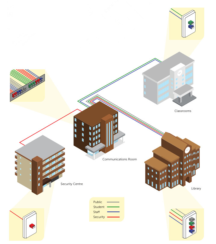
connectivity solution

FS.COM Keyed LC Connectivity Solutions
The secure keyed LC connectivity system is designed to respond to an urgent need for products that perform well for use in secure fiber networks. It offers great performance and reliability and can be installed very efficiently in all areas of a fiber cabling infrastructure. FS.COM keyed LC connectivity solutions are as follows.
The keyed LC fiber patch cables with color coded secure connectors and matching adapters prevent unauthorized access to secure fiber networks. They are used in interconnect or cross-connect fiber networks within a structured cabling system. We have the keyed LC fiber patch cables in single-mode 9/125 um, multimode 62.5/125 um, 50/125 um and laser-optimized 50/125 um for the most demanding network performance.

keyed LC patch cables
The keyed LC fiber optic adapters are keyed on both the front and back to prevent installation errors and avoid a possible security breach. Each coupler is color coded for identification and features a mechanical key. Our keyed couplers utilize a ceramic sleeve suitable for both single-mode and multimode applications.


keyed LC fiber optic adapters
The keyed LC fiber adapter panels are a widely recognized modular solution for restricted fiber cross-connect systems. They have specific color codes and functional keyed features to identify and manage restricted network cross connections. Application-specific networks with levels of security can be supported with keyed LC connections in the data center, equipment room and telecommunications room. FS.COM keyed LC fiber adapter panels are available in 12 fibers, 16 fibers and 24 fibers.

keyed LC fiber adapter panels
The keyed LC cassettes are designed to prevent unauthorized and inadvertent changes in highly sensitive applications such as data centers and secure IT networks. FS.COM MTP/MPO cassettes with keyed LC adapters provide mechanical security and prevent inadvertent cross connection between MTP and LC discrete connectors.

keyed LC cassettes 

Originally published: www.fiberopticshare.com

2016年6月24日星期五

High-density Cabling Solutions – Push-Pull TAB and LC Uniboot Fiber Patch Cables

In today’s data center and SAN environments, space is often at a premium, making density more critical than ever. Deploying high-density fiber optics offers advanced performance and reliability. This article will introduce two types of high-density fiber patch cables, which are push-pull TAB fiber patch cables and LC uniboot fiber patch cables.

Push-Pull TAB Fiber Patch Cables
The Push-pull TAB fiber patch cables have a special “pull” tab design, which features push-pull tab connector that offers maximum accessibility in high-density installations. It has the same components and internal-structure with the traditional patch cords, except a tab attached to the connector used for pushing or pulling the whole connector. With this design, the technician is able to finish the installing and removing procedures with only one hand and no additional tool are needed.

Two types of push-pull TAB fiber patch cables are available in the market. One is LC-HD TAB fiber patch cable, and the other is MPO-HD TAB fiber patch cable. The LC-HD TAB fiber patch cable is designed for the LC-HD switchable and movable connector. And its slim uni-boot design saves much space and makes cables more easily to be managed. With MTP/MPO connectors accommodating 12 fibers or 24 fibers, the MPO-HD TAB fiber patch cables provide up to 12 or 24 times the density, thereby offering savings in circuit card and rack space.
Push-Pull TAB fiber patch cables

Benefits of Push-Pull TAB Fiber Patch Cables
Compared with traditional fiber patch cables, the push-pull TAB patch cables are superior in the following aspects.

Easy to Release — Inserting and disconnecting patch cables can be challenging for fiber optic technicians in high-density environments such as 48-port 1U patch panels. The flexible "pull-tab" of the patch cables allows for the connector to be disengaged easily from densely loaded panels without the need for special tools. The technicians just need to push the tab forward to latch and gently pull the tab to release the connector from extremely dense fiber optic panels. Moreover, each fiber optic patch cable can be quickly identified by the labeling on the pull-tab.

LC-HD TAB fiber patch cable

Density Increase — As the connector of the patch cable can be released by using a simple pull tab, it eliminates the need for finger access to the connectors latch mechanism. Therefore, adapters can be mounted much closer than spacing required in the past.

Space Saving — The traditional connectors require a small vertical space above and below the adapters. While the low profile push-pull TAB patch cables, together with the pull tab, allow adapters to be stacked with absolutely no vertical space.

fiber patch cables

LC Uniboot Fiber Patch Cables
The LC uniboot fiber patch cables are utilized to achieve more effective cable management in high-density network environment. With a more compact design, they can reduce cable management space by 68% when compared to traditional duplex zipcord assemblies. These assemblies contain two LC connectors encased in a common housing with one boot, terminated on a single, round, two-fiber cable, therefore allowing duplex transmission within a single cable.
LC uniboot fiber patch cable
Benefits of LC Uniboot Fiber Patch Cables 
The LC uniboot fiber patch cables provide the following benefits with the special design and structure.

Polarity Reversible and Reduce Cable Congestion — With a finger latch release, the LC uniboot fiber patch cables eliminate the need for tools when making the polarity change. They are color-coded and labeled “A” and “B” to provide visual references when making a polarity flip. On top of the unique reversing polarity feature, the uniboot option cuts the amount of cabling by half compared to conventional duplex cords, greatly reducing cable congestion in racks and cabinets.

LC uniboot fiber patch cable

Easy Identification and Installation — The LC uniboot fiber patch cables offer improved airflow and visibility of equipment in high-density networks, which has definitely had a positive impact. The unique serial number, part number and length labeled on both ends of the cable help for easy identification. This also helps cut installation time in half for most the users. They are perfect for high-density applications where the cable footprint is critical.

Hassle-free Networking Configuration — With two individual LC connectors into a single entity, this design allows for a much cleaner appearance and hassle-free networking configuration, due to their ability to ensure communication integrity by preventing misconfiguration of the transmission and receiving fibers.

Conclusion
As the networking environment becomes increasingly dependent on high speed and high-density solutions, deploying the high-density fiber optic cables is undoubtedly an excellent choice. The Push-Pull TAB fiber patch cables and LC uniboot fiber patch cables can help to save space and reduce congestion, while providing manageability and flexibility. They offer the best solution for high-density applications in data centers.

Source: www.fiberopticshare.com/high-density-cabling-solutions-push-pull-tab-lc-uniboot-fiber-patch-cables.html

2016年6月9日星期四

Basic Knowledge About EDFA

In optical communication network, signals travel through fibers for very large distances without significant attenuation. However, when the signals need to transmit several hundreds of kilometers, it becomes necessary to amplify the signals during transit. EDFA (erbium doped fiber amplifier), commercialized in the early 1990's, became a key enabling technology for optical communication networks, and has deployed in the field. It enables the optical signals in an optical fiber to be amplified directly in high bit rate systems beyond Terabits. This article will introduce EDFA from the following aspects.

How Does Signal Amplification Happen?
The erbium doped fiber (EDF) is at the heart of EDFA technology. It is a conventional silica fiber doped with erbium. When the erbium is illuminated with light energy at a suitable wavelength (either 980 nm or 1480 nm), it is excited to a long lifetime intermediate state, following which it decays back to the ground state by emitting light within the 1525-1565nm band (see the following picture). If the light energy already exists within the 1525-2565nm band, for example due to a signal channel passing through the EDF, then this stimulates the decay process (so called stimulated emission), resulting in additional light energy. Thus, if a pump wavelength and a signal wavelength are simultaneously propagating through an EDF, energy transfer will occur via the erbium from the pump wavelength to the signal wavelength, resulting in signal amplification.

signal amplification

Components and Roles in EDFA Design
In its most basic form, the EDFA consists of a length of EDF (typically 10-30m), a pump laser, and a component (often referred to as a WDM) for combining the signal and pump wavelength so that they can propagate simultaneously through the EDF. In principle, EDFA can be designed such that pump energy propagates in the same direction as the signal (forward pumping), the opposite direction to the signal (backward pumping), or both direction together. The pump energy may either by 980nm pump energy, 1480nm pump energy, or a combination of both. Practically, the most common EDFA configuration is the forward pumping configuration using 980nm pump energy, as shown in the picture below. This configuration makes the most efficient use of cost effective, reliable and low power consumption 980nm semiconductor pump laser diodes, thus providing the best overall design with respect to performance and cost trade-offs.

EDFA components

Besides the three basic components described above, this picture also shows additional optical and electronic components used in a basic single stage EDFA. The signal enters the amplifier through the input port, and then passes through a tap which is used to divert a small percentage of the signal power (typically 1-2%) to an input detector. The signal then passes through an isolator, before being combined with pump energy emitted by the 980nm pump laser diode. The combined signal and pump energy propagate along the EDF, where signal amplification occurs, and then the amplified signal exits the EDF and passes through a second isolator. The purpose of the two isolators, which allow light to pass only in a single direction, is to ensure that lasing cannot take place with the EDF. Furthermore, the output isolator also acts as a filter for 980nm light propagating in the forward direction, thus stopping the 980nm light from exiting the amplifier output port.

Operating Modes of EDFA
An EDFA is typically operated in one of the two operating modes: AGC (automatic gain control) or APC (automatic power control). In the AGC mode, the amplifier gain is kept constant, whereas in APC mode, the amplifier output power is kept constant. While APC mode is used in some single channel applications, AGC mode is far more common, and is always used in multi-channel WDM applications. The following diagram shows AGC in an EDFA. Information from the input and output detectors is used to calculate the actual gain, which is then compared to the required gain. Based on this comparison, the pump current is then adjusted to change the actual gain towards the required gain. This is a classical feed-back control loop which can be implemented using analogue or digital circuitry. The response time of the control loop is dictated by the response of the EDF to changes in the pump power, which may be quite long (1ms and longer) due to the long lifetime of the Erbium ions' quasi-stable state.

operating mode of EDFA

Conclusion
A brief introduction to the EDFA, one of the most important components in WDM communications, is given in this article. Of the various technologies available for optical amplifiers, EDFA technology is by far the most advanced, and consequently the vast majority of optical amplifiers deployed to date are based on this technology. FS.COM provides various EDFA, including DWDM EDFA, CATV EDFA, etc. Visit www.fs.com for more details.

Article source: www.fiberopticshare.com/basic-knowledge-edfa.html