2016年2月24日星期三

40G/100G Implementation Technology Overview

For every few months, new technologies and solutions for 40G and 100G implementations will be come out. Demand for 40G and 100G transport links is growing rapidly. This paper will explore the implementation challenges, 40G/100G transport technologies and technology requirements respectively.

Implementation Challenges
 
Time to market is the major implementation challenge for companies introducing any new technology. The first company, demonstrating and implementing 40G and 100G links, has gained significant press coverage, developed early customer engagements and won important contracts. Time to market has become more important and more challenging because the 40G/100G market moves to second and third generation implementations.

Performance still remains a key implementation challenge for 40G/100G systems. 40G/100G systems need to meet similar distance and error rates as 10G systems, which requires tighter tolerances, enhanced modulation techniques and advanced signal processing technologies.

With the changing system requirements, 40G and 100G implementations need to be flexible. The systems might be able to support DWDM, OTN and Ethernet, and customers expect the latest functionality on these expensive interfaces. Flexibility can be achieved through the use of interchangeable boards and configurable devices.

40G/100G Transport Technologies
  • OTN (Optical Transport Network)
Packet-optical transport brings the benefits of Sonet/SDH, DWDM and packet-based networks together, delivering a scalable and resilient transport infrastructure. OTN is the underlying transport protocol supporting 2.5G (OTU1), 10G (OTU2), 40G (OTU3) and 100G (OTU4). Many carriers are shifting to OTN for their transport network.

The following picture shows a 40G packet-optical transport platform with a central OTN, Sonet/SDH and packet fabric switch. Optical line cards connect the system to the optical transport network. Transponders, muxponders and client cards connect the system to high-rate and low-rate OTN, Ethernet, Sonet/SDH and Fibre Channel networks. The system has 10G or 40G OTN line interfaces and many OTN, Ethernet, Fibre Channel or Sonet/SDH client interfaces. Micro optical transport platforms can be built using a single integrated packet-optical transport device.
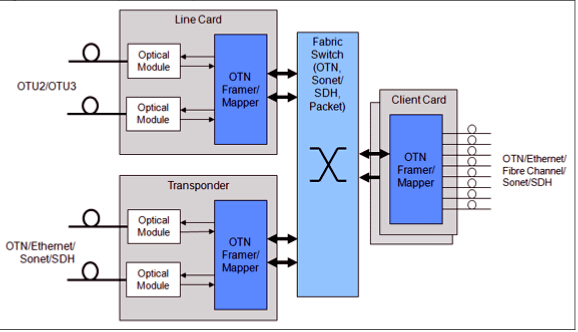
OTN
  • Ethernet
In June 2010, the standards for 40GE and 100GE were ratified. The specifications support 40GE and 100GE over single-mode fiber, multimode fiber, copper cable (up to 7m), and a system backplane. Ethernet can be sent over a fiber cable or transported over OTN.

The picture below shows a carrier Ethernet switch/router (CESR) with 10G/40G OTN line cards and 1G/10G Ethernet client interfaces. This system utilizes a mixture of OTN framer/mapper functions, Ethernet switch or network processor and multiple Ethernet MAC/PHY devices.
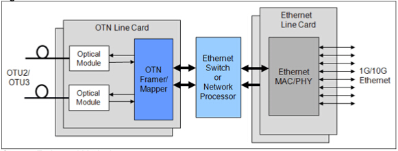
CESR with OTN
  • Optical Modules
Optical modules are widely used in telecom transport systems. The QSFP+ pluggable module is widely used for 40G applications. CFP, CFP2, and CFP4 optical modules are widely used for 100G applications.

Technology Requirements
 
High-speed serial I/O is a critical requirement for devices used in 40G/100G implementations. And 40G/100G systems require high-performance processing and switching functions. Digital signal processing is required for 100G coherent receiver implementations. Most systems also require switching, packet processing and control plane processor. 40G/100G systems require high-performance packet processing. This can be implemented using a dedicated network processor ASSP or by using proprietary or third-party IP to develop a FGPA or ASIC-based solution.

Conclusion
 
40G/100G networking presents some particular challenges for system developers. As stated above, time to market, performance and flexibility are the key parameters for implementation challenges. OTN, Ethernet and optical modules (QSFP+ module for 40G, CFP for 100G) are the necessary 40G/100G transport technologies.

Article source: www.fiberopticshare.com/40g100g-implementation-technology-overview.html

2016年2月17日星期三

Why Are 40G Active Optical Cables Popular?

40 Gigabit Ethernet is the trend of higher data transmission. Thus, 40G optical devices are gaining popularity, including 40G QSFP+ transceivers and 40G direct attach cables. 40G direct attach cable (DAC) provides a cost-effective solution for high-density network connectivity. It is a kind of high-speed cable which has transceivers on either end used to connect switches to routers or servers. DAC can be classified into direct attach copper cable and active optical cable.

40G active optical cable (AOC) is a type of active optical cable for 40GbE applications that is terminated with 40GBASE-QSFP+ on one end, while on the other end, besides QSFP+ connector, it can be terminated with SFP+ connectors, LC connectors, etc. 40G active optical cables have great advantages over 40G direct attach copper cables when transmission distance reaches up to 7 meters. Moreover, 40G AOC has lower weight and tighter bend radius, which enables simpler cable management.
40G active optical cables
Actually, 40GBASE-SR4 QSFP+ transceivers also have the above advantages. So why we highly recommend 40G AOC rather than 40GBASE-SR4 QSFP+ optics? The following section will tell the answer.

Firstly, 40G AOC has lower cost than 40GBASE-SR4 QSFP+ modules and does not need to use with extra fiber patch cables. Especially, 40G breakout active optical cables, such as 40GBASE QSFP+ to 8 x LC or 40GBASE QSFP+ to 4 x SFP+ are cost-effective solutions to achieve 40G migration. What’s more, if using AOC, there will be no cleanliness issues in optical connector and there is no need to do termination plug and test when troubleshooting, which can help end users save time and money.

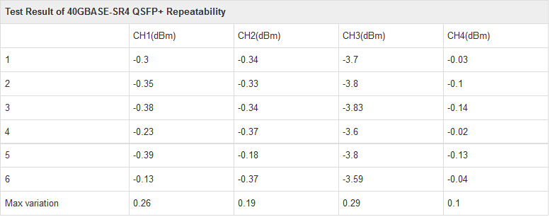
Insertion loss and return loss are the second factor. Under the same case of transmission distance, the repeatability and interchangeability performances of 40GBASE-SR4 module interface are not good as 40G AOC. Furthermore, when different fiber optic cables plug into the module, it will have the different insertion loss and return loss. Even for the same module, this issue is existed. Of course, the related metrics, such as the testing eye pattern, will have no significant changes so long as the variation in and conformed to the scope. In contrast, an AOC with good performance is more stable and has better swing performance than SR4 modules in this situation. The following table shows the result of the repeatability test of SR4 module. From the data, it is clear to see that the repeatability performance of SR4 module is not stable.

40GBASE-SR4 QSFP+

Thirdly, four-quadrant test, a testing under four combinations of input voltage and signal amplitude, is used to ensure the product to keep better performance even under the lowest and highest voltage and temperature situation. Four-quadrant test in wide temperature range is used to test MTP/MPO interface and optical cable of AOC to ensure them not to be melted in high temperature. Generally, the current products of AOC can satisfy this demand. Moreover, the performance of AOC is more stable than SR4 module which should be used with indeterminacy-performance MTP/MPO connectors. Unlike 40GBASE-SR4 module, the quality index of AOC is judged by electric eye pattern but not by light eye pattern.

Fourthly, digital diagnostic monitoring (DDM) can help end users to monitor real-time parameters of the modules. Such parameters include optical output power, optical input power, temperature, laser bias current, and transceiver supply voltage, etc. 40GBASE-SR4 QSFP+ transceiver with DDM function can ensure its optimal coupling by the ADC (analog to digital converters) value of real-time monitoring receiver when receive coupling. Thus, 40GBASE-SR4 modules have better receiving sensitivity than 40G AOC. However, at present, the 40GBASE-SR4 and AOC cannot reach the function of real-time power monitoring.

Transmission distance is the last factor. When transmitting over OM3 fiber, there is no significant difference between 40GBASE-SR4 and 40G AOC. But 40GBASE-SR4 has better performance control than 40G AOC. Moreover, proposals for transmission distance that is longer than 300 meters will be SR4 module in order to ensure a good performance.

From the above statements, we could see that 40G AOC has better consistency and repeatability cabling performance. Moreover, it can avoid the influence of environment and vibration, even for troubleshooting, AOC is more easier to manage. So active optical cable is highly recommended to use in data center interconnection. Fiberstore supplies various active optical cables and all of them can meet the ever increasing need to cost-effectively deliver more bandwidth, and can be customized to meet different requirements.

Article source: www.fiberopticshare.com/why-are-40g-active-optical-cables-popular.html

40G Ethernet Migration Strategy Over Multimode Fiber

With the increasing network bandwidth to meet the global IP traffic demand, there will be a need to upgrade to 40G Ethernet links for switch to server and storage area network connections in data centers. And the biggest market for 40G Ethernet (40 GbE) is in data centers for interconnection links with servers and storage area networks. So this article will talk about migration strategy for 40G Ethernet over multimode fiber.

40G Ethernet Standard
 
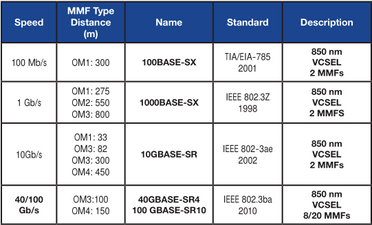
IEEE published the IEEE 802.3ba standard for 40 Gigabit Ethernet in June 2010. The following table illustrates the capabilities of different grades of multimode fibers (OM1, OM2, OM3 and OM4) to support different Ethernet applications. Only the laser optimized multimode fibers OM3 and OM4 are capable of supporting 40G Ethernet. The cabling requirements for 40GBASE-SR4 will be focused and guidance on an effective migration strategy to transition form 10G to 40G will be provided.

40G Ethernet Standard
 
40G Ethernet Over Multimode Fiber
 
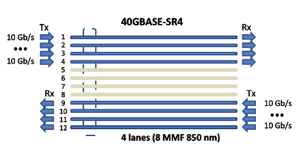
40G Ethernet over multimode fiber uses parallel optics at 10Gb/s per lane. One lane uses 1 fiber for each direction of transmission. 40G requires 8 fibers. The concept of parallel transmission at 10 Gigabits per lane is illustrated below. The minimum performance that is needed to support 40G over multimode fiber is OM3 fiber for a distance of 100 meters. Cabling with OM4 fiber provides the capability to extend the reach up to 150 meters.

40GBASE-SR4
 
Media Dependent Interface (MDI)
 
The MDI is the physical interface that connects the cabling media to the network equipment. For multimode fiber, the media dependent interface is the MPO adapter that meets the dimensional specifications of IEC 61754-7 interface 7-3. The corresponding MPO female plug on the optical fiber cable uses a flat interface that meets the dimensional specifications. 40 GbE uses the MPO connector interface at the MDI and uses a 12 position MPO connector interface that aligns 12 fibers in a single row. Four transmit fibers are used on one side and four receive fibers are used on the opposite side of the MPO connector, for a total of eight fibers. The middle four fiber positions are not used.

Migration Path From 10G to 40G for Multimode Fiber
 
Migrating from 10G (that uses two fibers in either a SC Duplex or a LC Duplex connector) to 40G will require a lot more fibers and a different type of connector. The way that optical fiber cabling is deployed for 10G can facilitate an easier migration path to 40G. An effective migration strategy needs to provide a smooth transition to the higher Ethernet speeds with minimum disruption and without wholesale replacement of existing cabling and connectivity components.

Optical fiber cabling is commonly deployed for backbone cabling in data centers for switch to switch connections and also for horizontal cabling for switch to server and storage area network connections. The use of pre-terminated optical fiber cabling can facilitate the migration path to 40G. A pre-terminated cable assembly containing 24 OM4 multimode fibers with two 12-fiber MPO connectors at both ends plugs into the back of a breakout cassette that splits the 24 fibers into 12 LC duplex connectors at the front of the cassette. It is necessary to provide some 40G connections, either as a replacement of or as an addition to the existing 10G connections.

The first case: if upgrading from 10G to 40G, one or more of the LC duplex cassette/cassettes can be replaced with 12 MPO adapters. The MPO adapters are designed to fit in the same opening as the cassettes. Fiberstore offers a high-density 18 MPO adapter with the same overall physical dimensions as 12 MPO adapter. This is an upgrade path from 10G to 40G that does not require any additional space and reuses the same patch panels. For instance, the 12 LC duplex cassettes could be replaced with either a 12 MPO or 18 MPO adapters as needed.

The second case: if it is required to add some 40G connections while retaining the 10G connections, a high-density cassette containing 18 LC duplex connections in the same space as a 12 LC duplex cassette would be used. Three of the 12 duplex cassettes can be replaced with three 18 LC Duplex cassettes, thus maintaining the 48 10G connections while freeing space for either a 12 MPO or 18 MPO adapter providing up to 18 additional 40G connections. The requisite number of additional fiber cable assemblies in multiples of 12 fibers are provided as needed.

Summary
 
Pre-terminated optical fiber cabling provides a seamless migration path to 40 Gigabit Ethernet using the same infrastructure by adding pre-terminated trunk cable assemblies and MPO adapter frames as needed. The use of Fiberstore’s pre-terminated cabling facilitates the migration to 40G Ethernet from 10G Ethernet networks today.

Article source: www.fiberopticshare.com/40g-ethernet-migration-strategy-over-multimode-fiber.html

2016年2月4日星期四

Which to Choose for 40GBASE-LR4 QSFP+ Transceiver: PSM or CWDM?

It is well known that 40GBASE-SR4 QSFP+ transceiver uses a parallel multimode fiber (MMF) link to achieve 40G. It offers four independent transmit and receive channels and each channel is capable of 10G operation for an aggregate data rate of 40G with distances up to 100 meters on OM3 MMF or 150 meters on OM4 MMF. However, for 40GBASE-LR4 QSFP+ transceivers, two kinds of links are available. One is parallel single-mode fiber (PSM), and the other is coarse wavelength division multiplexing (CWDM). What is the difference between the two? Keep reading this article and you will find the answer.

40GBASE-LR4 PSM QSFP+ Transceiver
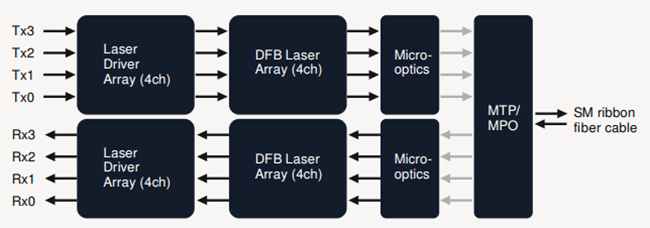
PSM QSFP+ transceiver is a parallel single-mode optical transceiver with an MTP/MPO fiber ribbon connector. Moreover, it offers four independent transmit and receive channels and each channel is capable of 10G operation for an aggregate data rate of 40G on 10 km of single-mode fiber. The guide pins inside the receptacle could ensure proper alignment. Usually, the cable cannot be twisted for proper channel to channel alignment. For a PSM QSFP+ transceiver, the transmitter module accepts electrical input signals compatible with common mode logic (CML) levels. All input data signals are differential and internally terminated. The receiver module converts parallel optical input signals via a photo detector array into parallel electrical output signals. The receiver module outputs electrical signals are also voltage compatible with CML levels. All data signals are differential and support a data rates up to 10.3G per channel.
40G PSM QSFP

40GBASE-LR4 CWDM QSFP+ Transceiver
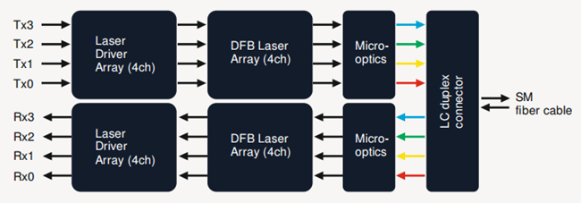
The 40GBASE-LR4 CWDM QSFP+ transceiver like QSFP-40GE-LR4 is compliant to 40GBASE-LR4 of the IEEE P802.3ba standard. It has a duplex LC connector for the optical interface and its maximum transmission distance is 10 kilometers. Single-mode fiber (SMF) has to be used to minimize the optical dispersion in the long-haul system. This transceiver converts 4 inputs channels of 10G electrical data to 4 CWDM optical signals by a driven 4-wavelength distributed feedback (DFB) laser array, and then multiplexes them into a single channel for 40G optical transmission, propagating out of the transmitter module from the SMF. Reversely, the receiver module accepts the 40G CWDM optical signals input, and demultiplexes it into four individual 10G channels with different wavelengths. The central wavelengths of the four CWDM channels are 1271, 1291, 1311 and 1331 nm as members of the CWDM wavelength grid defined in ITU-T G694.2. Moreover, each wavelength channel is collected by a discrete photo diode and output as electric data after being amplified by a transimpedance amplifier (TIA).
40GBASE-LR4 CWDM QSFP+ Transceiver

Differences Between the Two
From the perspective of an optical transceiver module structure, PSM seems more cost effective as it uses a single uncooled CW laser splitting its output power into four integrated silicon modulators. Moreover, its array-fiber coupling to an MTP connector is relatively simple. However, from the perspective of an infrastructure, PSM would be more expensive when the link distance is long, because it uses 8 optical single-mode fibers while CWDM only uses 2 optical single-mode fibers. The following table illustrates the main differences between CWDM and PSM.
difference between cwdm and psm

In addition, the caveat is that the entire optical fiber infrastructure within a data center, including patch panels, has to be changed to accommodate MTP connectors and ribbon cables, which are more expensive than conventional LC connectors and regular SMF cables. Moreover, it is not a straightforward tack to clean MTP connectors. So CWDM is a more profitable and popular 40G QSFP link.

Summary
For 40GBASE-LR4 QSFP+ transceivers, either CWDM link or PSM link, the maximum transmission distance is both 10 km. 40GBASE-LR4 PSM QSFP+ transceiver uses an MTP/MPO fiber ribbon connector via 8 optical single-mode fibers to reach 40G, while 40GBASE-LR4 CWDM QSFP+ transceiver uses a duplex LC connector via 2 optical single-mode fibers to achieve 40G. Thus, CWDM QSFP+ enables data center operators to upgrade to 40G connectivity without making any changes to the previous 10G fiber cable plant, which is more cost-effective and widely used by people.