2015年11月24日星期二

A Guide to Fiber Optic Splicing

Fiber Optic Splicing Basis
 
It is vital for any company or fiber optic technician involved in telecommunications to grasp knowledge of fiber optic splicing methods. Fiber optic splicing refers to joining two fiber optic cables together. It can result in lower light loss and back reflection. Two methods of fiber optic splicing are available: fusion splicing and mechanical splicing. Which technique best fits your economic and performance objectives? Keep reading the following statement and find the answer.

Fusion Splicing vs. Mechanical Splicing
 
Fusion splicing is an optical junction of two optical fibers by permanently welding them together with heat generated by an electronic arc (called arc fusion). It is the most widely used method of splicing because it provides least reflectance and lowest loss, as well as providing the strongest and most reliable joint between two fibers.
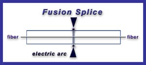
fusion splicing

Fusion splicing steps:
  1. Prepare the fiber: strip the protective coatings, jackets, tubes, strength members, and leave only the bare fiber showing. Pay attention to cleanliness.
  2. Cleave the fiber: using a good fiber optic cleaver here is essential to a successful fusion splice. The cleaved end must be mirror-smooth and perpendicular to the fiber axis to obtain a proper splice.
  3. Fuse the fiber: alignment and heating are the two steps within this step. Alignment can be automatic or manual depending upon the equipment you have. Once the fusion splicer unit are properly aligned, then you can use an electrical arc to melt the fibers and permanently weld the two fiber ends together.
  4. Protect the fiber: protecting the fiber from bending and tensile forces will ensure the splice not break during normal handling. Using heat shrink tubing, silicone gel and/or mechanical crimp protectors will keep the splice protected from outside elements and breakage.
Aligning and holding in place by a self-contained assembly, a mechanical splice is a junction of two or more optical fibers. Not permanently joined, the fibers are just precisely held together so that light can pass from one to another.

mechanical splicing

Mechanical splicing steps:
  1. Prepare the fiber: same with the step of fusion splicing.
  2. Cleave the fiber: the process is identical to the cleaving for fusion splicing.
  3. Mechanically join the fibers: simply position the fiber ends together inside the mechanical splice unit. The index matching gel inside the mechanical splice apparatus will help couple the light from one fiber end to the other.
  4. Protect the fiber: the completed mechanical splice will provide its own protection for the splice.
Tips for Better Splicing
 
  1. Clean your splicing tools thoroughly and frequently.
  2. Operate and maintain your cleaver properly.
  3. For fusion splicing, the fusion parameters must be adjusted minimally and methodically.
Which Method Is Better?
 
Cost and performance are the two deciding factors for choosing one method over the other. Mechanical splicing has a low initial investment ($1,000 - $2,000) but costs more per splice ($12-$40 each). Fusion splicing has lower cost per splice ($0.50 - $1.50 each) but higher initial investment ($15,000 - $50,000). As for the performance, fusion splicing produces lower loss and less back reflection than mechanical splicing. Fusion splices are primarily used with single-mode fiber, while mechanical splices work with both single-mode and multimode fiber.

Conclusion
 
To sum up, the two fiber optic splicing methods have its own advantages. Fusion splicing is invested for long haul single-mode networks, while mechanical splicing is used for shorter local cable runs. For better fiber optic splicing, besides the above splicing steps, high-quality fiber optic splicing tools are also essential, such as fusion splicers, fiber optic cleavers, etc. After all, good methods and excellent tools will produce the best performance.

Originally published: www.fiber-optic-components.com/a-guide-to-fiber-optic-splicing.html

2015年11月17日星期二

How to Optimize Data Center?

When talking about optimizing data center, what you actually want to know is a paradigm shift to a more cost-effective approach to IT data services. Data center optimization is the process of programming and increasing the efficiency of an enterprise’s data center operations. It can help to save your money and time as well as make your technology infrastructure more efficient. Good data center optimization is the difference between sprawling data, compute, and infrastructure spread out across multiple servers and ideal tight clusters, ready to be acted on. But how to optimize your data center? This is a question. Keep reading this article, and then you will get an answer.

Consolidation
 
Servers, storage, network and management — software defined and expertly integrated to save time and money is the latest trend in the data center. Consolidation is able to maximize resources, reduce footprint and save money by optimizing your computing, data, workload, automation and orchestration efforts.

Virtualization
 
Virtualization is about maximizing returns with minimal resources. Release your data center from the confines of the physical and abstract it into a virtual environment, then compose these virtual assets into a solution that makes your business run better.

Data Monitoring and Management
 
It is possible to gain end-to-end visibility of your crucial business processes, application and infrastructure. By using an intuitive user interface, you can monitor and manage your organization’s IT from one dashboard, which makes it much more easier to control what is happening in the infrastructure. Full visibility refers to the ability to predict problem before happening, and then you can make the necessary changes to free up or add necessary resources. Instead of relying on your Help Desk as the first line of error reporting, know that it’s happening ahead of time and have the problem fixed before it becomes an issue.

Automation and Orchestration
 
Free up your knowledge workers from the burden of busy work by automating and orchestrating the most repetitive parts of your workload. Automation and orchestration can help to reduce human errors. Then you can get back to focusing on what really matters. Streamline your processes, and discard the irrelevant ones, potentially outsourcing entire workflows to a policy-based automation. Orchestrate your data center into simplicity and efficiency.

Cloud Workload Migration
 
Cloud workload migration can help to optimize resources and improve performance efficiency. You need to understand what workloads are best moved to the cloud and how to move them efficiently and safely.

Push Yourself as Hard as You Push Your Data
 
You can take your IT and business decisions to a higher level by using your data efficiently. Ask some tough questions that will help to make you more competitive and efficient, and then task your data professionals and IT department with providing the right answers. Finally, scale your questions so that you are pushing yourself and your data to new levels of operational efficiency.

From the above statement, have you got some ideas about how to get your data center optimized? FS.COM is a professional supplier of optical products, such as 10G SFP+, 40G/100G transceiver, etc. It is a wise choice to select data center products from Fiberstore to fill your data center operation system.

Originally published: www.fiber-optic-components.com/how-to-optimize-data-center.html

2015年11月10日星期二

Why Is Fiber Cleaning Necessary?

At a BICSI Conference in 2008, JDSU stated, “Contamination is the number-one reason for troubleshooting optical networks.” For the long-term reliability of any network, fiber cleaning is critical and it is at the heart of the profitability of successful fiber deployment. This paper will introduce the necessity of fiber cleaning and then give two tips on fiber protection against dust contamination.

Four reasons for fiber cleaning are listed below:

Signal Failure
As you know, fiber optic networks work by carrying pulses of light between transmitters and receivers. Contamination and dirt will block the signal and lead to light loss, reducing power and efficiency. The amount of light loss shrinks correspondingly as links carry higher data rates, which makes cleaning even more essential. Dirty equipment can give rise to network failure or paralysis.

Equipment Failure
Dirt can cause permanent damage to the end-face, digging into the surface and creating pits that increase back reflection. Failures in the network caused by dirt can increase costs and install time because damaged equipment may need to be tracked down and replaced, which means more time on-site and greater expenditure. Both of the two will impact the overall budget for a deployment.

Angry Occupants
It is naturally going to enrage consumers and building owners by leaving a mess in a subscriber’s home or the common areas of an apartment building. They’d like to have the benefits of fiber broadband rather than the dirt or damage to their property when it is installed.

Adopting Proper Cleanliness Procedures
While it is easy to focus on more visible debris, dirt is most dangerous at a microscopic level, particularly when it comes to the end-faces of connectors. For example, simply touching the ferrules of a connector will deposit significant amounts of body oil onto the end face. Best practice for this issue is to use high-grade, completely lint-free wipes (aiming for clean room quality) and pure Isopropyl Alcohol (IPA).

On top of this, here are two areas to keep an especially close eye on:

Mating and Unmating
The actual process of mating and unmating connectors can also cause damage to the ceramic. Therefore, aim to minimize this plugging and unplugging as much as possible and ensure you inspect the two end-faces for dirt or debris that could be crushed between them. This can cause permanent damage, such as scratches, cracks or pits that will require re-termination, not just cleaning. Moreover, make sure you inspect any other equipment ports that the connector is being plugged into, as they can also harbour contamination.

Don’t Rely on Dust Caps
Many people may think that if you don’t take the dust cap off your factory terminated connector until you plug it in, it’ll keep dirt free. After all, it was packaged in a sterile factory environment. In fact, dust caps are preventing damage to the end-face, rather than stopping all contamination reaching the connector.

Fiberstore Fiber Cleaning Solution
As a professional supplier in the optical industry, Fiberstore has various high-quality and low-price fiber optic cleaning tools, such as fiber connector cleaner, optical connector cleaning cards, one click fiber optic cleaner for 1.25mm connectors, etc. These tools can help to ease or remove all kinds of dirty particles, such as dust, dripping and moist. Choosing any kind of fiber optic cleaning tools in Fiberstore will give you a surprise!

2015年11月3日星期二

SFP+ Transceiver Testing – TWDPc Measurement

SFP+ transceiver is widely deployed in applications and becomes much more pervasive due to its smaller form factor, less power consumption and its increased port density compared with XFP transceiver. Each SFP+ transceiver houses an optical receiver and transmitter. One end of the transceiver is an optical connection complying with the 10GbE and 8GFC standards, while the other end is an SERDES framer interface (SFI) serial interconnect handling differential signals up to 10 Gbit/s. In order to keep a SFP+ transceiver achieving high performance, the engineers need to acquaint with the key challenges related to testing SFP+ transceiver. This article will first walk through the SFP+ testing challenges and then focus on one kind of testing measurement.

SFP+ Testing Challenges
  • One obvious challenge is the increased port density and the testing time required with 48 or more ports per rack.
  • Another challenge is moving seamlessly from a compliance environment to a debug environment.
  • Yet another problem most designers face today relates to connectivity: how to get the signal out from the device under test (DUT) to an oscilloscope.
  • Another challenge to prepare for is that the SFP+ specification calls out some measurements to be performed using a PRBS31 signal.
  • Additionally, acquiring a record length of 200 million data points demands huge processing power and time.
TWDPc Measurement

TWDPc, short for transmitter waveform distortion penalty for copper, requires a special algorithm defined by the SFP+ specification. This test is defined as a measure of the deterministic dispersion penalty due to a particular transmitter with reference to the emulated multimode fibers and a well-characterized receiver.

TWDPc-measurement

The TWDPc script (of 802.3aq, 10GBASE-LRM) processes a PRBS9 pattern requiring at least 16 samples per unit interval. Out of concern for the large installed base of equivalent-time oscilloscopes with a record length of around 4000 samples, the requirement for 16 samples per unit interval was relaxed to seven samples per unit interval.

The relaxation of the requirement from 16 samples per unit interval to just seven samples per unit interval causes worst-case pessimism of 0.24 dB TWDPc over 30 measurements. For DUTs that already have a high TWDPc, 0.24 dB can be the difference between a pass or a fail result.

The TWDPc measurement for SFP+ host transmitter output specifications for copper requires more than 70 Gsamples/s to capture a minimum of seven samples per UI. Real-time oscilloscopes offering higher sampling rates of 100 Gsamples/s or greater have a much higher chance of providing accurate results for TWDPc compared to scopes that only offer lower sampling-rate options.

Across the board, it is important to map the SFP+ signal’s data-transfer rate to the proper oscilloscope bandwidth requirements to ensure accuracy in measurement and margin testing. With a 10.3125-Gbyte/s data-transfer rate and minimum rise time of 34 ps, a scope with a bandwidth of 16 GHz or higher is required to meet the minimum requirements for SFP+. As noted, sampling rate is also an important consideration for the TWDPc measurement.

Conclusion

Although SFP+ transceiver simplifies the functionality of the 10G optical module, it introduces some test and measurement challenges. TWDPc is a key test for SFP+ transceiver. It defines the differences (in dB) between a reference signal and noise ratio (SNR) and the equivalent SNR at the slicer input of a reference equalizer receiver for the measurement waveform after propagating through a stimulus channel. For SFP+ compliance testing, TWDPc is a required measurement.